
Vivado Design Suite User
Guide
Logic Simulaon
UG900 (v2022.1) April 21, 2022
See all versions
of this document
Xilinx is creating an environment where employees, customers, and
partners feel welcome and included. To that end, we’re removing non-
inclusive language from our products and related collateral. We’ve
launched an internal initiative to remove language that could exclude
people or reinforce historical biases, including terms embedded in our
software and IPs. You may still find examples of non-inclusive
language in our older products as we work to make these changes and
align with evolving industry standards. Follow this link for more
information.

Table of Contents
Chapter 1: Overview......................................................................................................7
Navigating Content by Design Process.................................................................................... 7
Logic Simulation Overview.........................................................................................................7
Supported Simulators.................................................................................................................8
Simulation Flow .......................................................................................................................... 8
Language and Encryption Support ........................................................................................ 11
Chapter 2: Preparing for Simulation..................................................................12
Using Test Benches and Stimulus Files.................................................................................. 12
Pointing to the Simulator Install Location............................................................................. 13
Compiling Simulation Libraries............................................................................................... 14
Using Xilinx Simulation Libraries.............................................................................................19
Using Simulation Settings........................................................................................................ 28
Adding or Creating Simulation Source Files.......................................................................... 32
Generating a Netlist..................................................................................................................34
Chapter 3: Simulating with Third-Party Simulators................................. 37
Running Simulation Using Third Party Simulators with Vivado IDE................................... 38
Dumping SAIF for Power Analysis...........................................................................................41
Dumping VCD............................................................................................................................ 43
Simulating IP..............................................................................................................................44
Using a Custom DO File During an Integrated Simulation Run.......................................... 44
Running Third-Party Simulators in Batch Mode....................................................................46
Chapter 4: Simulating with Vivado Simulator..............................................47
Running the Vivado Simulator.................................................................................................47
Running Functional and Timing Simulation...........................................................................65
Saving Simulation Results........................................................................................................ 68
Distinguishing Between Multiple Simulation Runs...............................................................68
Closing a Simulation................................................................................................................. 69
Adding a Simulation Start-up Script File.................................................................................69
Viewing Simulation Messages................................................................................................. 70
UG900 (v2022.1) April 21, 2022 www.xilinx.com
Vivado Design Suite User Guide: Logic Simulation 2

Using the launch_simulation Command................................................................................ 72
Re-running the Simulation After Design Changes (relaunch).............................................73
Using the Saved Simulator User Interface Settings..............................................................74
Chapter 5: Analyzing Simulation Waveforms with Vivado
Simulator...................................................................................................................... 76
Using Wave Configurations and Windows.............................................................................76
Opening a Previously Saved Simulation Run.........................................................................77
Understanding HDL Objects in Waveform Configurations .................................................78
Customizing the Waveform..................................................................................................... 81
Controlling the Waveform Display .........................................................................................87
Organizing Waveforms.............................................................................................................91
Analyzing Waveforms............................................................................................................... 93
Analyzing AXI Interface Transactions..................................................................................... 98
Chapter 6: Debugging a Design with Vivado Simulator....................... 113
Debugging at the Source Level............................................................................................. 113
Forcing Objects to Specific Values.........................................................................................117
Power Analysis Using Vivado Simulator............................................................................... 125
Using the report_drivers Tcl Command................................................................................127
Using the Value Change Dump Feature...............................................................................127
Using the log_wave Tcl Command........................................................................................ 128
Cross Probing Signals in the Object, Wave, and Text Editor Windows.............................130
Chapter 7: Simulating in Batch or Scripted Mode in Vivado
Simulator.....................................................................................................................136
Exporting Simulation Files and Scripts................................................................................. 136
Running the Vivado Simulator in Batch Mode.....................................................................142
Elaborating and Generating a Design Snapshot, xelab......................................................144
Simulating the Design Snapshot, xsim.................................................................................155
Example of Running Vivado Simulator in Standalone Mode.............................................159
Project File (.prj) Syntax..........................................................................................................160
Predefined Macros..................................................................................................................161
Library Mapping File (xsim.ini).............................................................................................. 161
Running Simulation Modes....................................................................................................162
Using Tcl Commands and Scripts .........................................................................................165
export_simulation ...................................................................................................................166
export_ip_user_files.................................................................................................................169
UG900 (v2022.1) April 21, 2022 www.xilinx.com
Vivado Design Suite User Guide: Logic Simulation 3

Appendix A: Compilation, Elaboration, Simulation, Netlist, and
Advanced Options..................................................................................................172
Compilation Options...............................................................................................................172
Elaboration Options................................................................................................................174
Simulation Options................................................................................................................. 176
Netlist Options.........................................................................................................................178
Advanced Simulation Options............................................................................................... 179
Appendix B: SystemVerilog Support in Vivado Simulator................... 180
Targeting SystemVerilog for a Specific File..........................................................................180
Testbench Feature...................................................................................................................187
Appendix C: Universal Verification Methodology Support................. 196
Appendix D: VHDL 2008 Support in Vivado Simulator............................197
Introduction ............................................................................................................................ 197
Compiling and Simulating......................................................................................................197
Supported Features................................................................................................................ 199
Appendix E: Direct Programming Interface (DPI) in Vivado
Simulator.....................................................................................................................201
Introduction............................................................................................................................. 201
Compiling C Code....................................................................................................................201
xsc Compiler............................................................................................................................ 202
Binding Compiled C Code to SystemVerilog Using xelab.................................................. 204
Data Types Allowed on the Boundary of C and SystemVerilog......................................... 204
Mapping for User-Defined Types..........................................................................................205
Support for svdpi.h Functions............................................................................................... 207
DPI Examples Shipped with the Vivado Design Suite.........................................................215
Appendix F: SystemC Support in Vivado IDE............................................... 216
Selecting Simulation Model Type.......................................................................................... 216
Protected Models.................................................................................................................... 220
Unprotected Models............................................................................................................... 221
SystemC Simulation Using Vivado........................................................................................ 222
Running SystemC Simulation Using Vivado Simulator.......................................................224
Appendix G: Automated Testbench Generation for Sub-Design..... 225
UG900 (v2022.1) April 21, 2022 www.xilinx.com
Vivado Design Suite User Guide: Logic Simulation 4

generate_vcd_ports.................................................................................................................225
create_testbench..................................................................................................................... 226
Using Automated Testbench Generation on Example Design.......................................... 227
Appendix H: Handling Special Cases................................................................231
Using Global Reset and 3-State............................................................................................. 231
Delta Cycles and Race Conditions......................................................................................... 233
Using the ASYNC_REG Constraint..........................................................................................234
Simulating Configuration Interfaces.................................................................................... 236
Disabling Block RAM Collision Checks for Simulation........................................................ 239
Dumping the Switching Activity Interchange Format File for Power Analysis................ 240
Skipping Compilation or Simulation..................................................................................... 240
Appendix I: Value Rules in Vivado Simulator Tcl Commands............ 242
String Value Interpretation.................................................................................................... 242
Vivado Design Suite Simulation Logic.................................................................................. 242
Appendix J: Vivado Simulator Mixed Language Support and
Language Exceptions........................................................................................... 244
Using Mixed Language Simulation....................................................................................... 244
VHDL Language Support Exceptions....................................................................................250
Verilog Language Support Exceptions ................................................................................ 251
Appendix K: Vivado Simulator Quick Reference Guide......................... 254
Appendix L: Using Xilinx Simulator Interface............................................ 257
Preparing the XSI Functions for Dynamic Linking.............................................................. 257
Writing the Test Bench Code................................................................................................. 259
Compiling Your C/C++ Program............................................................................................ 260
Preparing the Design Shared Library................................................................................... 260
XSI Function Reference...........................................................................................................261
Vivado Simulator VHDL Data Format....................................................................................266
Vivado Simulator Verilog Data Format................................................................................. 269
Appendix M: Additional Resources and Legal Notices.......................... 272
Xilinx Resources.......................................................................................................................272
Documentation Navigator and Design Hubs...................................................................... 272
References................................................................................................................................272
Links to Additional Information on Third-Party Simulators...............................................273
UG900 (v2022.1) April 21, 2022 www.xilinx.com
Vivado Design Suite User Guide: Logic Simulation 5

Training Resources..................................................................................................................274
Revision History.......................................................................................................................274
Please Read: Important Legal Notices................................................................................. 275
UG900 (v2022.1) April 21, 2022 www.xilinx.com
Vivado Design Suite User Guide: Logic Simulation 6

Chapter 1
Overview
Navigating Content by Design Process
Xilinx
®
documentaon is organized around a set of standard design processes to help you nd
relevant content for your current development task. All Versal
®
ACAP design process Design
Hubs and the Design Flow Assistant materials can be found on the Xilinx.com website. This
document covers the following design processes:
• Hardware, IP, and Plaorm Development: Creang the PL IP blocks for the hardware
plaorm, creang PL kernels, funconal simulaon, and evaluang the Vivado
®
ming,
resource use, and power closure. Also involves developing the hardware plaorm for system
integraon. Topics in this document that apply to this design process include:
• Chapter 3: Simulang with Third-Party Simulators
• Chapter 4: Simulang with Vivado Simulator
• Appendix F: SystemC Support in Vivado IDE
Logic Simulation Overview
Simulaon is a process of emulang real design behavior in a soware environment. Simulaon
helps verify the funconality of a design by injecng smulus and observing the design outputs.
This chapter provides an overview of the simulaon process, and the simulaon opons in the
Vivado
®
Design Suite.
The process of simulaon includes:
• Creang test benches, seng up libraries and specifying the simulaon sengs for Simulaon
• Generang a Netlist (if performing post-synthesis or post-implementaon simulaon)
• Running a Simulaon using Vivado simulator or third party simulators. See Supported
Simulators for more informaon on supported simulators.
Chapter 1: Overview
UG900 (v2022.1) April 21, 2022 www.xilinx.com
Vivado Design Suite User Guide: Logic Simulation 7
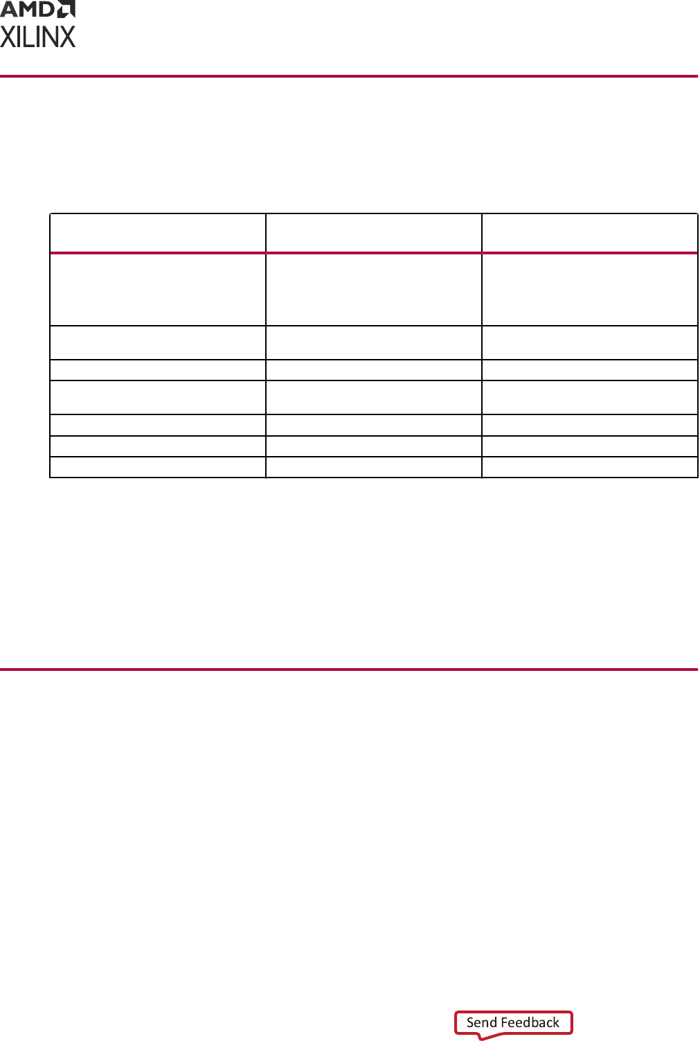
Supported Simulators
Following are the supported simulators in the Vivado Design Suite:
Table 1: Supported Simulators
Simulator Version
Integrated with Vivado
Integrated Design Environment
Vivado
®
Simulator 2022.1 Integrated with the Vivado integrated
design environment, where each
simulation launch appears as a
framework of windows within the
Vivado IDE.
Siemens EDA Questa Advanced
Simulator
2021.3 Yes
Siemens EDA ModelSim Simulator 2021.3 Yes
Synopsys Verilog Compiler Simulator
(VCS)
S-2021.09 Yes
Aldec Rivera-PRO Simulator 2021.04 Yes
Aldec Active-HDL 12.0 Yes
Cadence Xcelium Parallel Simulator 21.09.002 Yes
See the Vivado Design Suite User Guide: Release Notes, Installaon, and Licensing (UG973) for the
supported versions of third-party simulators.
For more informaon about the Vivado IDE and the Vivado Design Suite ow, see:
• Vivado Design Suite User Guide: Using the Vivado IDE (UG893)
• Vivado Design Suite User Guide: Design Flows Overview (UG892)
Simulation Flow
Simulaon can be applied at several points in the design ow. It is one of the rst steps aer
design entry and one of the last steps aer implementaon as part of verifying the end
funconality and performance of the design.
Simulaon is an iterave process and is typically repeated unl both the design funconality and
ming requirements are sased.
The following gure illustrates the simulaon ow for a typical design:
Chapter 1: Overview
UG900 (v2022.1) April 21, 2022 www.xilinx.com
Vivado Design Suite User Guide: Logic Simulation 8
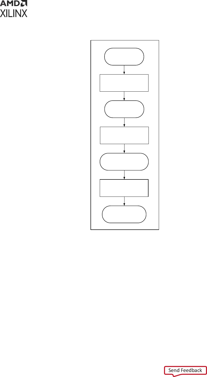
Figure 1: Simulation Flow
Behavioral Simulation
(Verify Design Behaves as
Intended)
Synthesize
RTL Design
Post Synthesis Simulation
Implement (Place and
Route)
Post Implementation
Simulation
(Close to Emulating HW)
Debug the Design
X23703-021320
Behavioral Simulation at the Register Transfer Level
Register Transfer Level (RTL) behavioral simulaon can include:
• RTL Code
• Instanated UNISIM library components
• Instanated UNIMACRO components
• UNISIM gate-level model (for the Vivado logic analyzer)
• SECUREIP Library
RTL-level simulaon lets you simulate and verify your design prior to any translaon made by
synthesis or implementaon tools. You can verify your designs as a module or an enty, a block,
a device, or a system.
Chapter 1: Overview
UG900 (v2022.1) April 21, 2022 www.xilinx.com
Vivado Design Suite User Guide: Logic Simulation 9

RTL simulaon is typically performed to verify code syntax, and to conrm that the code is
funconing as intended. In this step, the design is primarily described in RTL and consequently,
no ming informaon is required.
RTL simulaon is not architecture-specic unless the design contains an instanated device
library component. To support instanaon, Xilinx
®
provides the UNISIM library.
When you verify your design at the behavioral RTL you can x design issues earlier and save
design cycles.
Keeping the inial design creaon limited to behavioral code allows for:
• More readable code
• Faster and simpler simulaon
• Code portability (the ability to migrate to dierent device families)
• Code reuse (the ability to use the same code in future designs)
Post-Synthesis Simulation
You can simulate a synthesized netlist to verify that the synthesized design meets the funconal
requirements and behaves as expected. Although it is not typical, you can perform ming
simulaon with esmated ming numbers at this simulaon point.
The funconal simulaon netlist is a hierarchical, folded netlist expanded to the primive module
and enty level; the lowest level of hierarchy consists of primives and macro primives.
These primives are contained in the UNISIMS_VER library for Verilog, and the UNISIM library
for VHDL.
Related Information
UNISIM Library
Post-Implementation Simulation
You can perform funconal or ming simulaon aer implementaon. Timing simulaon is the
closest emulaon to actually downloading a design to a device. It allows you to ensure that the
implemented design meets funconal and ming requirements and has the expected behavior in
the device.
IMPORTANT!
Performing a thorough ming simulaon ensures that the completed design is free of
defects that could otherwise be missed, such as:
Chapter 1: Overview
UG900 (v2022.1) April 21, 2022 www.xilinx.com
Vivado Design Suite User Guide: Logic Simulation 10

• Post-synthesis and post-implementaon funconality changes that are caused by:
○ Synthesis properes or constraints that create mismatches (such as full_case and
parallel_case)
○ UNISIM properes applied in the Xilinx Design Constraints (XDC) le
○ The interpretaon of language during simulaon by dierent simulators
• Dual port RAM collisions
• Missing, or improperly applied ming constraints
• Operaon of asynchronous paths
○ Funconal issues due to opmizaon techniques
Language and Encryption Support
The Vivado simulator supports:
• VHDL, see IEEE Standard VHDL Language Reference Manual (IEEE-STD-1076-1993) and part
of VHDL-2008.
• Verilog, see IEEE Standard Verilog Hardware Descripon Language (IEEE-STD-1364-2001).
• SystemVerilog, see IEEE Standard for SystemVerilog--Unied Hardware Design, Specicaon,
and Vericaon Language (IEEE-STD-1800-2009).
• IEEE P1735 encrypon, see Recommended Pracce for Encrypon and Management of
Electronic Design Intellectual Property (IP) (IEEE-STD-P1735).
Chapter 1: Overview
UG900 (v2022.1) April 21, 2022 www.xilinx.com
Vivado Design Suite User Guide: Logic Simulation 11

Chapter 2
Preparing for Simulation
This chapter describes the components that you need when you simulate a Xilinx
®
device in the
Vivado
®
Integrated Design Environment (IDE).
Set up the following before performing the simulaon:
• Create a test bench that reects the simulaon acons you want to run.
• Set up an install locaon in Vivado IDE (if not using the Vivado simulator).
• Compile your libraries (if not using the Vivado simulator).
• Select and declare the libraries you need to use.
• Specify the simulaon sengs such as target simulator, the simulaon top module name, top
module (design under test), display the simulaon set, and dene the compilaon, elaboraon,
simulaon, netlist, and advanced opons.
• Generate a Netlist (if performing post-synthesis or post-implementaon simulaon).
Using Test Benches and Stimulus Files
A test bench is Hardware Descripon Language (HDL) code wrien for the simulator that:
• Instanates and inializes the design.
• Generates and applies smulus to the design.
• Monitors the design output result and checks for funconal correctness (oponal).
You can also set up the test bench to display the simulaon output to a le, a waveform, or to a
display screen. A test bench can be simple in structure and can sequenally apply smulus to
specic inputs.
A test bench can also be complex, and can include:
• Subroune calls
• Smulus that is read in from external les
• Condional smulus
• Other more complex structures
Chapter 2: Preparing for Simulation
UG900 (v2022.1) April 21, 2022 www.xilinx.com
Vivado Design Suite User Guide: Logic Simulation 12

The advantages of a test bench over interacve simulaon are that it:
• Allows repeatable simulaon throughout the design process
• Provides documentaon of the test condions
The following bullets are recommendaons for creang an eecve test bench.
• Always specify the `timescale in Verilog test bench les. For example:
`timescale 1ns/1ps
• Inialize all inputs to the design within the test bench at simulaon me zero to properly
begin simulaon with known values.
• Apply smulus data aer 100 ns to account for the default Global Set/Reset (GSR) pulse used
in funconal and ming-based simulaon.
• Begin the clock source before the Global Set/Reset (GSR) is released.
For more informaon about test benches, see Wring Ecient Test Benches (XAPP199).
TIP: When you create a test bench, remember that the GSR pulse occurs automacally in the post-
synthesis and post-implementaon ming simulaon. This holds all registers in reset for the rst 100 ns of
the simulaon.
Related Information
Using Global Reset and 3-State
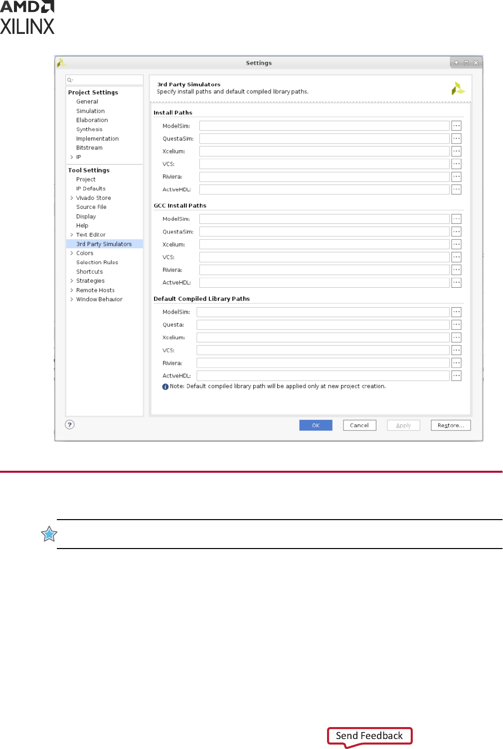
Pointing to the Simulator Install Location
To dene the installaon path:
1. Select Tools → Sengs → Tool Sengs → 3rd Party Simulators.
2. In Third-Party simulators tab of the Sengs dialog box, select the simulator under the Install
Paths as shown in the following gure, and browse to the installaon path.
3. Select the appropriate simulator under Default Compiled Library Paths and browse to the
relevant compiled library paths. You can set the library paths at a later point of me. See
Compiling Simulaon Libraries for more informaon on how to compile libraries for your
simulator.
Note: Installing Vivado simulator is part of Vivado IDE Installaon. Hence, you do not need to setup an
install locaon for Vivado simulator.
Chapter 2: Preparing for Simulation
UG900 (v2022.1) April 21, 2022 www.xilinx.com
Vivado Design Suite User Guide: Logic Simulation 13
Compiling Simulation Libraries
IMPORTANT!
With Vivado simulator, there is no need to compile the simulaon libraries. However, you
must compile the libraries when using a third-party simulator.
The Vivado Design Suite provides simulaon models as a set of les and libraries. Your simulaon
tool must compile these les prior to design simulaon. The simulaon libraries contain the
device and IP behavioral and ming models. The compiled libraries can be used by mulple
design projects.
Chapter 2: Preparing for Simulation
UG900 (v2022.1) April 21, 2022 www.xilinx.com
Vivado Design Suite User Guide: Logic Simulation 14
During the compilaon process, Vivado creates a default inializaon le that the simulator uses
to reference the compiled libraries. The compile_simlib command creates the le in the
library output directory specied during library compilaon. The default inializaon le contains
control variables that specify reference library paths, opmizaon, compiler, and simulator
sengs. If the correct inializaon le is not found in the path, you cannot run simulaon on
designs that include Xilinx primives.
The name of the inializaon le varies depending on the simulator you are using, as follows:
• Questa Advanced Simulator/ModelSim: modelsim.ini
• Xcelium: cds.lib
• VCS: synopsys_sim.setup
• Riviera/Acve-HDL: library.cfg
For more informaon on the simulator-specic compiled library le, see the third-party
simulaon tool documentaon.
IMPORTANT! Compilaon of the libraries is typically a one-me operaon, as long as you are using the
same version of tools. However, any change to the Vivado tools or the simulator versions requires that
libraries be recompiled.
You can compile libraries using the Vivado IDE or using Tcl commands, as described in the
following secons.
Compiling Simulation Libraries Using Vivado IDE
Select Tools → Compile Simulaon Libraries to open the dialog box shown in the following gure.
Chapter 2: Preparing for Simulation
UG900 (v2022.1) April 21, 2022 www.xilinx.com
Vivado Design Suite User Guide: Logic Simulation 15
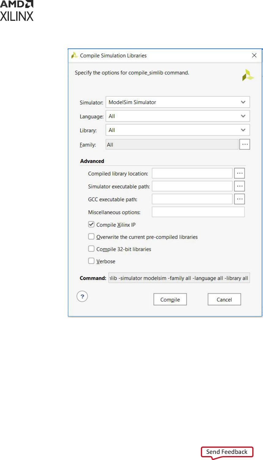
Figure 2: Compile Simulation Libraries Dialog Box
Set the following opons:
• Simulator: From the simulator drop-down menu, select a simulator.
• Language: Compiles libraries for the specied language. If this opon is not specied, then the
language is set to correspond with the selected simulator (above). For mul-language
simulators, both Verilog and VHDL libraries are compiled.
• Library: Species the simulaon library to compile. By default, the compile_simlib
command compiles all simulaon libraries.
• Family: Compiles selected libraries to the specied device family. All device families are
generated by default.
Chapter 2: Preparing for Simulation
UG900 (v2022.1) April 21, 2022 www.xilinx.com
Vivado Design Suite User Guide: Logic Simulation 16

• Compiled library locaon: Species the directory path for saving the compiled library results.
By default, the libraries are saved in the current working directory in Non-Project mode, and
the libraries are saved in the <project>/<project>.cache/compile_simlib directory
in Project mode. See the Vivado Design Suite User Guide: Design Flows Overview (UG892) for
more informaon on Project and Non-Project modes.
TIP: Because the Vivado simulator has pre-compiled libraries, it is not necessary to idenfy the library
locaon.
• Simulator executable path: Species the directory to locate the simulator executable. This
opon is required if the target simulator is not specied in the $PATH or %PATH% environment
variable, or to override the path from the $PATH or %PATH% environment variable.
• GCC executable path: Species the directory to locate GCC installaon. This opon is
required if GCC path sengs are not done as menoned in GCC Path Sengs. Ignore if you
are not using SystemC IP.
• Miscellaneous Opons: Specify addional opons for the compile_simlib Tcl command.
• Compile Xilinx IP: Enable or disable compiling simulaon libraries for Xilinx IP.
• Overwrite current pre-compiled libraries: Overwrites the current pre-compiled libraries.
• Compile 32-bit libraries: Performs simulator compilaon in 32-bit mode instead of the default
64-bit compilaon.
• Verbose: Temporarily overrides any message limits and return all messages from this
command.
• Command: Shows the Tcl command equivalent for the opons you enter in the dialog box.
TIP: You can use the value of the Command eld to generate a simulaon library in Tcl/non-project
mode.
Compiling Simulation Libraries Using Tcl Commands
Alternavely, you can compile simulaon libraries using the compile_simlib Tcl command.
For details, see compile_simlib in the Vivado Design Suite Tcl Command Reference Guide
(UG835), or type compile_simlib -help.
Following are example commands for each third-party simulator:
• Questa Advanced Simulator: Generang a simulaon library for Questa for all languages and
for all libraries and all families in the current directory.
compile_simlib -language all -simulator questa -library all -family all
Chapter 2: Preparing for Simulation
UG900 (v2022.1) April 21, 2022 www.xilinx.com
Vivado Design Suite User Guide: Logic Simulation 17

• ModelSim: Generang simulaon library for ModelSim at /a/b/c, where the ModelSim
executable path is <simulator_installation_path>.
compile_simlib -language all -dir {/a/b/c} -simulator modelsim -
simulator_exec_path
{<simulator_installation_path>} -library all -family all
• VCS: Generang a simulaon library for VCS for the Verilog language, for the UNISIM library
at /a/b/c.
compile_simlib -language verilog -dir {/a/b/c} -simulator vcs_mx -library
unisim
-family all
• Xcelium: Generang a simulaon library for Xcelium for the Verilog language, for the UNISIM
library at /a/b/c.
compile_simlib -language verilog -dir {/a/b/c} -simulator xcelium -
library unisim
-family all
Changing compile_simlib Defaults
The config_compile_simlib Tcl command lets you congure third-party simulator opons
for use by the compile_simlib command.
Tcl Command
config_compile_simlib [-cfgopt <arg>] [-simulator <arg>] [-reset] [-quiet]
[-verbose]
Where:
• -cfgopt <arg>: Conguraon opon in form of
<simulator>:<language>:<library>:<options>.
• -simulator: The name of the simulator whose conguraon you want
• -reset: Lets you reset all previous conguraons for the specied simulator
• -quiet: Executes the command without any display to the Tcl Console.
• -verbose: Executes the command with all command output to the Tcl Console.
For example, to change the opon used to compile the UNISIM VHDL library, type:
config_compile_simlib {cxl.modelsim.vhdl.unisim:-source -93 -novopt}
IMPORTANT!
The
compile_simlib
command compiles Xilinx primives and Simulaon models of
Xilinx Vivado IP. Xilinx Vivado IP cores are delivered as an output product when the IP is generated;
consequently they are included in the pre-compiled libraries created using
compile_simlib
.
Chapter 2: Preparing for Simulation
UG900 (v2022.1) April 21, 2022 www.xilinx.com
Vivado Design Suite User Guide: Logic Simulation 18

Compiling Patched IP Repository in a New Output Directory Using MYVIVADO
Assume that the patched IP repository is at the following locaon:
'/test/patched_ip_repo/data/ip/xilinx'
To compile the default installed IP repository and the repository that is pointed to by MYVIVADO
in a new output directory, set the MYVIVADO environment (env) variable to point to this patched
IP repository and run compile_simlib. compile_simlib will process the IP library sources
from the default installed repository and the one set by MYVIVADO.
% setenv MYVIVADO /test/patched_ip_repo
% compile_simlib -simulator <simulator> -directory <new_clibs_dir>
Compiling Patched IP Repository in an Existing Output Directory Using MYVIVADO
Assume that the patched IP repository is at the following locaon:
'/test/patched_ip_repo/data/ip/xilinx'
To compile the repository pointed to by MYVIVADO in an exisng output directory where the
library was already compiled for the default installed IP repository, set the MYVIVADO env
variable to point to this patched IP repository and run compile_simlib. compile_simlib
will process the IP library sources from the repository set by MYVIVADO in the exisng output
directory.
% setenv MYVIVADO /test/patched_ip_repo
% compile_simlib -simulator <simulator> -directory <existing_clibs_dir>
Using Xilinx Simulation Libraries
You can use Xilinx simulaon libraries with any simulator that supports the VHDL-93 and
Verilog-2001 language standards. Certain delay and modeling informaon is built into the
libraries; this is required to simulate the Xilinx hardware devices correctly.
Use non-blocking assignments for blocks within clocking edges. Otherwise, write code using
blocking assignments in Verilog. Similarly, use variable assignments for local computaons within
a process, and use signal assignments when you want data-ow across processes.
If the data changes at the same me as a clock, it is possible that the simulator will schedule the
data input to occur aer the clock edge. The data does not go through unl the next clock edge,
although it is possible that the intent was to have the data clocked in before the rst clock edge.
RECOMMENDED:
To avoid such unintended simulaon results, do not switch data signals and clock
signals simultaneously.
Chapter 2: Preparing for Simulation
UG900 (v2022.1) April 21, 2022 www.xilinx.com
Vivado Design Suite User Guide: Logic Simulation 19
When you instanate a component in your design, the simulator must reference a library that
describes the funconality of the component to ensure proper simulaon. The Xilinx libraries are
divided into categories based on the funcon of the model.
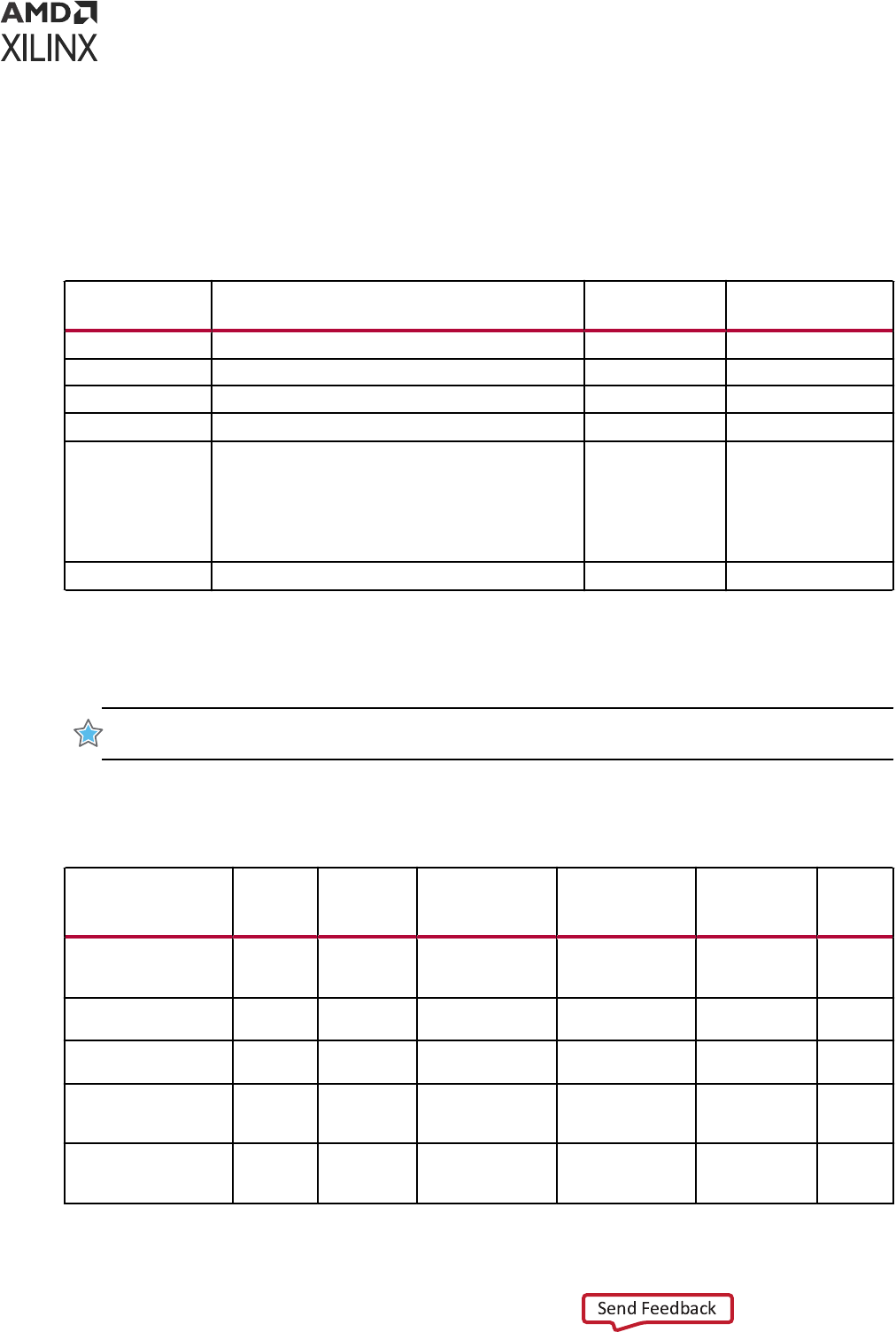
The following table lists the Xilinx-provided simulaon libraries:
Table 2: Simulation Libraries
Library Name Description
VHDL Library
Name
Verilog Library
Name
UNISIM
Functional simulation of Xilinx primitives.
UNISIM UNISIMS_VER
UNIMACRO
Functional simulation of Xilinx macros.
UNIMACRO UNIMACRO_VER
UNIFAST
Fast simulation library.
UNIFAST UNIFAST_VER
SIMPRIM
Timing simulation of Xilinx primitives. N/A SIMPRIMS_VER
1
SECUREIP
Simulation library for both functional and timing
simulation of Xilinx device features, such as the PCIe
IP, Gigabit Transceiver etc.,
You can find the list of IP's under SECUREIP at the
following location:
<Vivado_Install_Dir>/data/secureip
SECUREIP SECUREIP
XPM
Functional simulation of Xilinx primitives
XPM
XPM
2
Notes:
1. The SIMPRIMS_VER is the logical library name to which the Verilog SIMPRIM physical library is mapped.
2. XPM is supported as a pre-compiled IP. Hence, you need not add the source file to the project. For third party
simulators, the Vivado tools will map to pre-compiled IP generated with compile_simlib.
IMPORTANT! You must specify dierent simulaon libraries according to the simulaon points. There are
dierent gate-level cells in pre- and post-implementaon netlists.
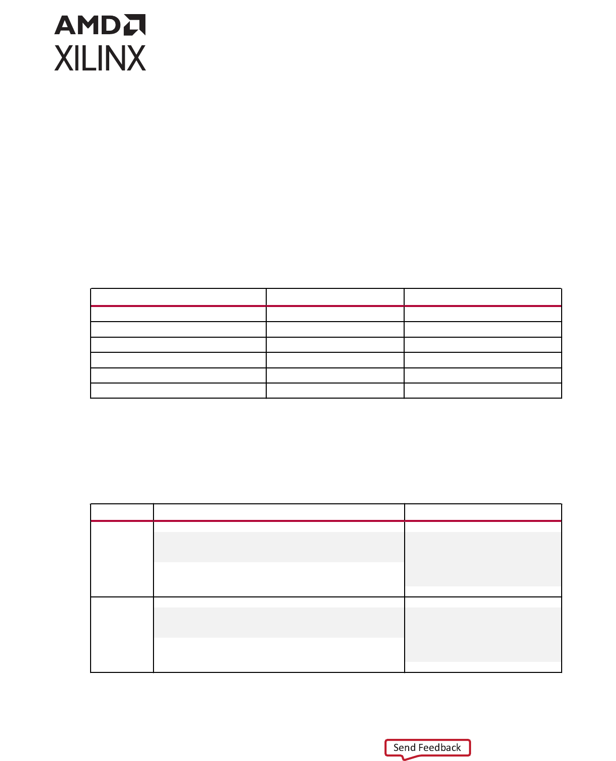
The following table lists the required simulaon libraries at each simulaon point.
Table 3: Simulation Points and Relevant Libraries
Simulation Point UNISIM UNIFAST UNIMACRO SECUREIP
SIMPRIM
(Verilog
Only)
SDF
1. Register Transfer
Level (RTL)
(Behavioral)
Yes Yes Yes Yes N/A No
2. Post-Synthesis
Simulation (Functional)
Yes Yes N/A Yes N/A N/A
3. Post-Synthesis
Simulation (Timing)
N/A N/A N/A Yes Yes Yes
4. Post-
Implementation
Simulation (Functional)
Yes Yes N/A Yes N/A N/A
5. Post-
Implementation
Simulation (Timing)
N/A N/A N/A Yes Yes Yes
Chapter 2: Preparing for Simulation
UG900 (v2022.1) April 21, 2022 www.xilinx.com
Vivado Design Suite User Guide: Logic Simulation 20
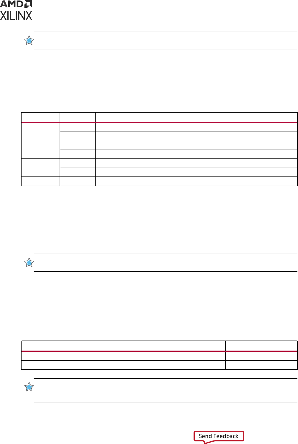
IMPORTANT! The Vivado simulator uses precompiled simulaon device libraries. When updates to
libraries are installed the precompiled libraries are automacally updated.
Note: Verilog SIMPRIMS_VER uses the same source as UNISIM with the addion of specify blocks for
ming annotaon. SIMPRIMS_VER is the logical library name to which the Verilog physical SIMPRIM is
mapped.
The following table lists the library locaons.
Table 4: Simulation Library Locations
Library HDL Type Location
UNISIM
Verilog
<Vivado_Install_Dir>/data/verilog/src/unisims
VHDL
<Vivado_Install_Dir>/data/vhdl/src/unisims
UNIFAST
Verilog
<Vivado_Install_Dir>/data/verilog/src/unifast
VHDL
<Vivado_Install_Dir>/data/vhdl/src/unifast
UNIMACRO
Verilog
<Vivado_Install_Dir>/data/verilog/src/unimacro
VHDL
<Vivado_Install_Dir>/data/vhdl/src/unimacro
SECUREIP
Verilog
<Vivado_Install_Dir>/data/secureip/
The following subsecons describe the libraries in more detail.
UNISIM Library
Funconal simulaon uses the UNISIM library and contains descripons for device primives or
lowest-level building blocks.
IMPORTANT!
By default, the
compile_simlib
command compiles the stac simulaon les for all
the IP's in the IP Catalog.
Encrypted Component Files
The following table lists the UNISIM library component les that let you call precompiled,
encrypted library les when you include IP in a design. Include the path you require in your
library search path.
Table 5: Component Files
Component File Description
<Vivado_Install_Dir>/data/verilog/src/unisim_retarget_comp.vp
Encrypted Verilog file
<Vivado_Install_Dir>/data/vhdl/src/unisims/unisim_retarget_VCOMP.vhdp
Encrypted VHDL file
IMPORTANT! Verilog module names and le names are uppercase. For example, module BUFG is
BUFG.v
, and module IBUF is
IBUF.v
. Ensure that UNISIM primive instanaons adhere to an
uppercase naming convenon.
Chapter 2: Preparing for Simulation
UG900 (v2022.1) April 21, 2022 www.xilinx.com
Vivado Design Suite User Guide: Logic Simulation 21

VHDL UNISIM Library
The VHDL UNISIM library is divided into the following les, which specify the primives for the
Xilinx device families:
• The component declaraons (unisim_VCOMP.vhd)
• Package les (unisim_VPKG.vhd)
To use these primives, place the following two lines at the beginning of each le:
library UNISIM;
use UNISIM.VCOMPONENTS.all;
IMPORTANT! You must also compile the library and map the library to the simulator. The method
depends on the simulator.
Note: For Vivado simulator, the library compilaon and mapping is an integrated feature with no further
user compilaon or mapping required.
Note: Starng in Versal
®
ACAP, Xilinx is delivering Verilog/SystemVerilog models only for the new
primives. This does mean that a mixed-language environment is needed for VHDL-only designs, like what
has been needed in the past for IPs and XPMs. For more informaon, see AR76496.
Verilog UNISIM Library
In Verilog, the individual library modules are specied in separate HDL les. This allows the -y
library specicaon switch to search the specied directory for all components and automacally
expand the library.
The Verilog UNISIM library cannot be specied in the HDL le prior to using the module. To use
the library module, specify the module name using all uppercase leers.
The following example shows the instanated module name as well as the le name associated
with that module:
• Module BUFG is BUFG.v
• Module IBUF is IBUF.v
Verilog is case-sensive, ensure that UNISIM primive instanaons adhere to an uppercase
naming convenon.
If you use precompiled libraries, use the correct simulator command-line switch to point to the
precompiled libraries. The following is an example for the Vivado simulator:
-L unisims_ver
Where:
-L is the library specicaon opon.
Chapter 2: Preparing for Simulation
UG900 (v2022.1) April 21, 2022 www.xilinx.com
Vivado Design Suite User Guide: Logic Simulation 22

UNIMACRO Library
The UNIMACRO library is used during funconal simulaon and contains macro descripons for
selected device primives.
IMPORTANT! You must specify the UNIMACRO library anyme you include a device macro listed in the
Vivado Design Suite 7 Series FPGA and Zynq-7000 SoC Libraries Guide (UG953).
VHDL UNIMACRO Library
To use these primives, place the following two lines at the beginning of each le:
library UNIMACRO;
use UNIMACRO.Vcomponents.all;
Verilog UNIMACRO Library
In Verilog, the individual library modules are specied in separate HDL les. This allows the -y
library specicaon switch to search the specied directory for all components and automacally
expand the library.
The Verilog UNIMACRO library does not need to be specied in the HDL le prior to using the
modules as is required in VHDL. To use the library module, specify the module name using all
uppercase leers. You must also compile and map the library; the method you use depends on
the simulator you choose.
IMPORTANT!
Verilog module names and le names are uppercase. For example, module BUFG is
BUFG.v
. Ensure that UNIMACRO primive instanaons adhere to an uppercase naming convenon.
SIMPRIM Library
Use the SIMPRIM library for simulang ming simulaon netlists produced aer synthesis or
implementaon.
IMPORTANT!
Timing simulaon is supported in Verilog only; there is no VHDL version of the SIMPRIM
library.
TIP: If you are a VHDL user, you can run post synthesis and post implementaon funconal simulaon (in
which case no standard default format (SDF) annotaon is required and the simulaon netlist uses the
UNISIM library). You can create the netlist using the write_vhdl Tcl command. For usage informaon, refer
to the Vivado Design Suite Tcl Command Reference Guide (UG835).
Following is an example for specifying the library for Vivado simulator:
-L SIMPRIMS_VER
Where:
Chapter 2: Preparing for Simulation
UG900 (v2022.1) April 21, 2022 www.xilinx.com
Vivado Design Suite User Guide: Logic Simulation 23
• -L is the library specicaon opon.
• SIMPRIMS_VER is the logical library name to which the Verilog SIMPRIM has been mapped.
SECUREIP Simulation Library
Use the SECUREIP library for funconal and ming simulaon of complex device components,
such as GT.
Note: Secure IP Blocks are fully supported in the Vivado simulator without addional setup.
Xilinx leverages the encrypon methodology as specied in the IEEE standard Recommended
Pracce for Encrypon and Management of Electronic Design Intellectual Property (IP) (IEEE-STD-
P1735). The library compilaon process automacally handles encrypon.
Note: See the simulator documentaon for the command line switch to use with your simulator to specify
libraries.
The following table lists special consideraons that must be arranged with your simulator vendor
for using these libraries.
Table 6: Special Considerations for Using SECUREIP Libraries
Simulator Name Vendor Requirements
Siemens EDA ModelSim SE Siemens If design entry is in VHDL, a mixed language license or a SECUREIP
OP is required. Contact the vendor for more information.
Siemens EDA Questa Advanced
Simulator
VCS Synopsys
Active-HDL Aldec If design entry is VHDL, a mixed language license is required.
Riviera-PRO*
IMPORTANT! See Vivado Design Suite User Guide: Release Notes, Installaon, and Licensing (UG973) for
the supported version of third-party simulators.
VHDL SECUREIP Library
The UNISIM library contains the wrappers for VHDL SECUREIP. Place the following two lines at
the beginning of each le so that the simulator can bind to the enty:
Library UNISIM;
UNISIM.VCOMPONENTS.all;
Verilog SECUREIP Library
When running a simulaon using Verilog code, you must reference the SECUREIP library for
most simulators.
Chapter 2: Preparing for Simulation
UG900 (v2022.1) April 21, 2022 www.xilinx.com
Vivado Design Suite User Guide: Logic Simulation 24
If you use the precompiled libraries, use the correct direcve to point to the precompiled
libraries. The following is an example for the Vivado simulator:
-L SECUREIP
IMPORTANT! You can use the Verilog SECUREIP library at compile me by using
-f
switch. The le list is
available in the following path:
<Vivado_Install_Dir>/data/secureip/
secureip_cell.list.f
.
UNIFAST Library
The UNIFAST library is an oponal library that you can use during RTL behavioral simulaon to
speed up simulaon runme.
IMPORTANT! The UNIFAST library is an oponal library that you can use during funconal simulaon to
speed up simulaon runme. UNIFAST libraries are supported for 7 series devices only. UltraScale and
later device architectures do not support UNIFAST libraries, as all the opmizaons are incorporated in the
UNISIM libraries by default. UNIFAST libraries cannot be used for sign-o simulaons because the library
components do not have all the checks/features that are available in a full model.
RECOMMENDED: Use the UNIFAST library for inial vericaon of the design and then run a complete
vericaon using the UNISIM library.
The simulaon run me improvement is achieved by supporng a subset of the primive
features in the simulaon mode.
Note: The simulaon models check for unsupported aribute values only.
MMCME2
To reduce the simulaon runmes, the fast MMCME2 simulaon model has the following
changes from the full model:
1. The fast simulaon model provides only basic clock generaon funcons. Other funcons,
such as DRP, ne phase shiing, clock stopped, and clock cascade are not supported.
2. It assumes that input clock is stable without frequency and phase change. The input clock
frequency sampling stops aer LOCKED signal is asserted HIGH.
3. The output clock frequency, phase, duty cycle, and other features are directly calculated from
input clock frequency and parameter sengs.
Note: The output clock frequency is not generated from input-to-VCO clock.
4. The standard and the fast MMCME2 simulaon model LOCKED signal asseron mes dier.
• Standard Model LOCKED asseron me depends on the M and D seng. For large M and
D values, the lock me is relavely long for a standard MMCME2 simulaon model.
• In the fast simulaon model, the LOCKED asseron me is shortened.
Chapter 2: Preparing for Simulation
UG900 (v2022.1) April 21, 2022 www.xilinx.com
Vivado Design Suite User Guide: Logic Simulation 25

DSP48E1
To reduce the simulaon runmes, the fast DSP48E1 simulaon model has the following features
removed from the full model.
• Paern Detecon
• OverFlow/UnderFlow
• DRP interface support
GTHE2_CHANNEL/GTHE2_COMMON
To reduce the simulaon runmes, the fast GTHE2 simulaon model has the following feature
dierences:
• GTH links must be synchronous with no Parts Per Million (PPM) rate dierences between the
near and far end link partners.
• Latency through the GTH is not cycle accurate with the hardware operaon.
• You cannot simulate the DRP producon reset sequence. Bypass it when using the UNIFAST
model.
Using Verilog UNIFAST Library
To reduce the simulaon runmes, the fast GTXE2 simulaon model has the following feature
dierences:
• GTX links must be of synchronous with no Parts Per Million (PPM) rate dierences between
the near and far end link partners.
• Latency through the GTX is not cycle accurate with the hardware operaon.
Method 1: Using the complete Verilog UNIFAST library (Recommended)
Method 1 is the recommended method whereby you simulate with all the UNIFAST models.
Use the following Tcl command in Tcl console to enable UNIFAST support (fast simulaon
models) in a Vivado project environment for the Vivado simulator, ModelSim or VCS:
set_property unifast true [current_fileset –simset]
See the UNISIM Library for more informaon regarding component les.
For more informaon, see the appropriate third-party simulaon user guide.
Method 2: Using specific UNIFAST modules
Recommended for more advanced users who want to specify which modules to simulate with
the UNIFAST models.
Chapter 2: Preparing for Simulation
UG900 (v2022.1) April 21, 2022 www.xilinx.com
Vivado Design Suite User Guide: Logic Simulation 26

To specify individual library components, Verilog conguraon statements are used. Specify the
following in the config.v le:
• The name of the top-level module or conguraon (for example: config cfg_xilinx;)
• The name to which the design conguraon applies (for example: design test bench;)
• The library search order for cells or instances that are not explicitly called out (for example:
default liblist unisims_ver unifast_ver;)
• The map for a parcular CELL or INSTANCE to a parcular library (For example: instance
testbench.inst.O1 use unifast_ver.MMCME2;)
Note: For ModelSim (vsim) only -genblk is added to hierarchy name (for example: instance
testbench.genblk1.inst.genblk1.O1 use unifast_ver.MMCME2; - VSIM).
Example config.v
config cfg_xilinx;
design testbench;
default liblist unisims_ver unifast_ver;
//Use fast MMCM for all MMCM blocks in design
cell MMCME2 use unifast_ver.MMCME2;
//use fast dSO48E1for only this specific instance in the design
instance testbench.inst.O1 use unifast_ver.DSP48E1;
//If using ModelSim or Questa, add in the genblk to the name
(instance testbench.genblk1.inst.genblk1.O1 use unifast_ver.DSP48E1)
endconfig
Using VHDL UNIFAST Library
The VHDL UNIFAST library has the same basic structure as Verilog and can be used with
architectures or libraries. You can include the library in the test bench le.
The following example uses a drill-down hierarchy with a for call:
library unisim;
library unifast;
configuration cfg_xilinx of testbench
is for xilinx
.. for inst:netlist
. . . use entity work.netlist(inst);
.......for inst
.........for all:MMCME2
..........use entity unifast.MMCME2;
.........end for;
.......for O1 inst:DSP48E1;
.........use entity unifast.DSP48E1;
.......end for;
...end for;
..end for;
end for;
end cfg_xilinx;
Note: If you want to use a VHDL UNIFAST model, you have to use a conguraon to bind the UNIFAST
library during elaboraon.
Chapter 2: Preparing for Simulation
UG900 (v2022.1) April 21, 2022 www.xilinx.com
Vivado Design Suite User Guide: Logic Simulation 27
Using Simulation Settings
You can use the simulaon sengs to specify the target simulator, display the simulaon set, the
simulaon top module name, top module (design under test), tabbed lisng of compilaon,
elaboraon, simulaon, netlist, and advanced opons. From the Vivado IDE Flow Navigator,
right-click Simulaon and select Simulaon Sengs to open the Simulaon Sengs in the
Sengs dialog box, as shown in the following gure.
Figure 3: Settings Dialog Box
The Sengs dialog box includes the following simulaon sengs:
• Target simulator: From the simulator drop-down menu, select a simulator. Vivado
®
simulator
is the default simulator. However, many third-party simulators are also supported.
Chapter 2: Preparing for Simulation
UG900 (v2022.1) April 21, 2022 www.xilinx.com
Vivado Design Suite User Guide: Logic Simulation 28

• Simulator language: Select the simulator language mode. The simulaon model used for
various IPs in your design varies depending on what language the IP supports.
• Simulaon set: Select the simulaon set that the simulaon commands use by default.
IMPORTANT! The compilaon and simulaon sengs for a previously dened simulaon set are not
applied to a newly-dened simulaon set.
• Simulaon top module name: Enter an alternate top module to use during simulaon.
• Generate simulaon scripts only: Generates scripts if selected. Simulaon is not invoked.
• Compiled library locaon: This opon is displayed when you select a third party simulator.
This is a directory path for saving the compiled library results. By default, the libraries are
saved in the current working directory in Non-Project mode. The libraries are saved in the
<project>/<project>.cache/compile_simlib directory in project mode.
• Compilaon tab: This tab denes and manages compiler direcves, which are stored as
properes on the simulaon leset and used by the xvlog and xvhdl ulies to compile Verilog
and VHDL source les for simulaon.
Note: xvlog and xvhdl are Vivado simulator specic commands. The applicable ulies will change
based on the target simulator.
• Elaboraon tab: This tab denes and manages elaboraon direcves, which are stored as
properes on the simulaon leset and used by the xelab ulity for elaborang and
generang a simulaon snapshot. Select a property in the table to display a descripon of the
property and edit the value.
Note: xelab is a Vivado simulator specic command. The applicable ulies will change based on the
target simulator.
• Simulaon tab: This tab denes and manages simulaon direcves, which are stored as
properes on the simulaon leset and used by the xsim applicaon for simulang the current
project. Select a property in the table to display a descripon of the property and edit the
value.
• Netlist tab: This tab provides access to netlist conguraon opons related to SDF annotaon
of the Verilog netlist and the process corner captured by SDF delays. These opons are stored
as properes on the simulaon leset and are used while wring the netlist for simulaon.
• Advanced tab: This tab contains two opons:
• Enable incremental compilaon: This opon enables the incremental compilaon and
preserves the simulaon les during successive run.
• Include all design sources for simulaon: By default, this opon is enabled. Selecng this
opon ensures that all the les from design sources along with the les from the current
simulaon set will be used for simulaon. Even if you change the design sources, the same
changes will be updated when you launch behavioral simulaon.
Chapter 2: Preparing for Simulation
UG900 (v2022.1) April 21, 2022 www.xilinx.com
Vivado Design Suite User Guide: Logic Simulation 29

CAUTION! Changing the sengs in the Advanced tab should be done only if necessary. The Include
all design sources for simulaon check box is selected by default. Deselecng the box could produce
unexpected results. As long as the check box is selected, the simulaon set includes Out-of-Context
(OOC) IP, IP Integrator les, and DCP.
Note: For detailed informaon on the properes in the Compilaon, Elaboraon, Simulaon, Netlist,
and Advanced tabs, see Appendix A: Compilaon, Elaboraon, Simulaon, Netlist, and Advanced
Opons.
Understanding the Simulator Language Option
Most Xilinx IP deliver behavioral simulaon models for a single language only, eecvely
disabling simulaon for language-locked simulators if you are not licensed for the appropriate
language. The simulator_language property ensures that an IP delivers a simulaon model
for any given language. For example, if you are using a single language simulator, you set the
simulator_language property to match the language of the simulator.
The Vivado Design Suite ensures the availability of a simulaon model by using the available
synthesis les of an IP to generate a language-specic structural simulaon model on demand.
For cases in which a behavioral model is missing or does not match the licensed simulaon
language, the Vivado tools automacally generate a structural simulaon model to enable
simulaon. Otherwise, the exisng behavioral simulaon model for the IP is used. If no synthesis
or simulaon les exist, simulaon is not supported.
Note: The simulator_language property cannot deliver a language-specic simulaon netlist le if the
generated Synthesized checkpoint (.dcp) is disabled.
1. In the Flow Navigator, click IP Catalog to open the IP catalog.
2. Right-click the appropriate IP and select Customize IP from the popup menu.
3. In the Customize IP dialog box, click OK.
The Generate Output Products dialog box (shown in the following gure) opens.
Chapter 2: Preparing for Simulation
UG900 (v2022.1) April 21, 2022 www.xilinx.com
Vivado Design Suite User Guide: Logic Simulation 30
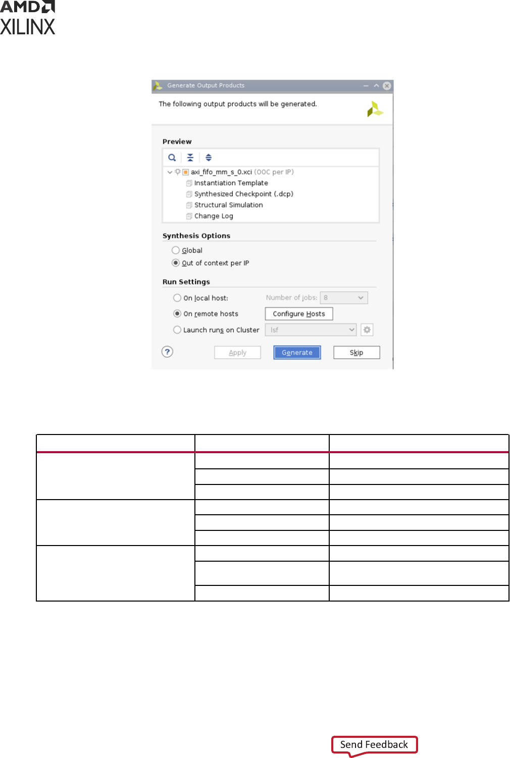
Figure 4: Generate Output Products Dialog Box
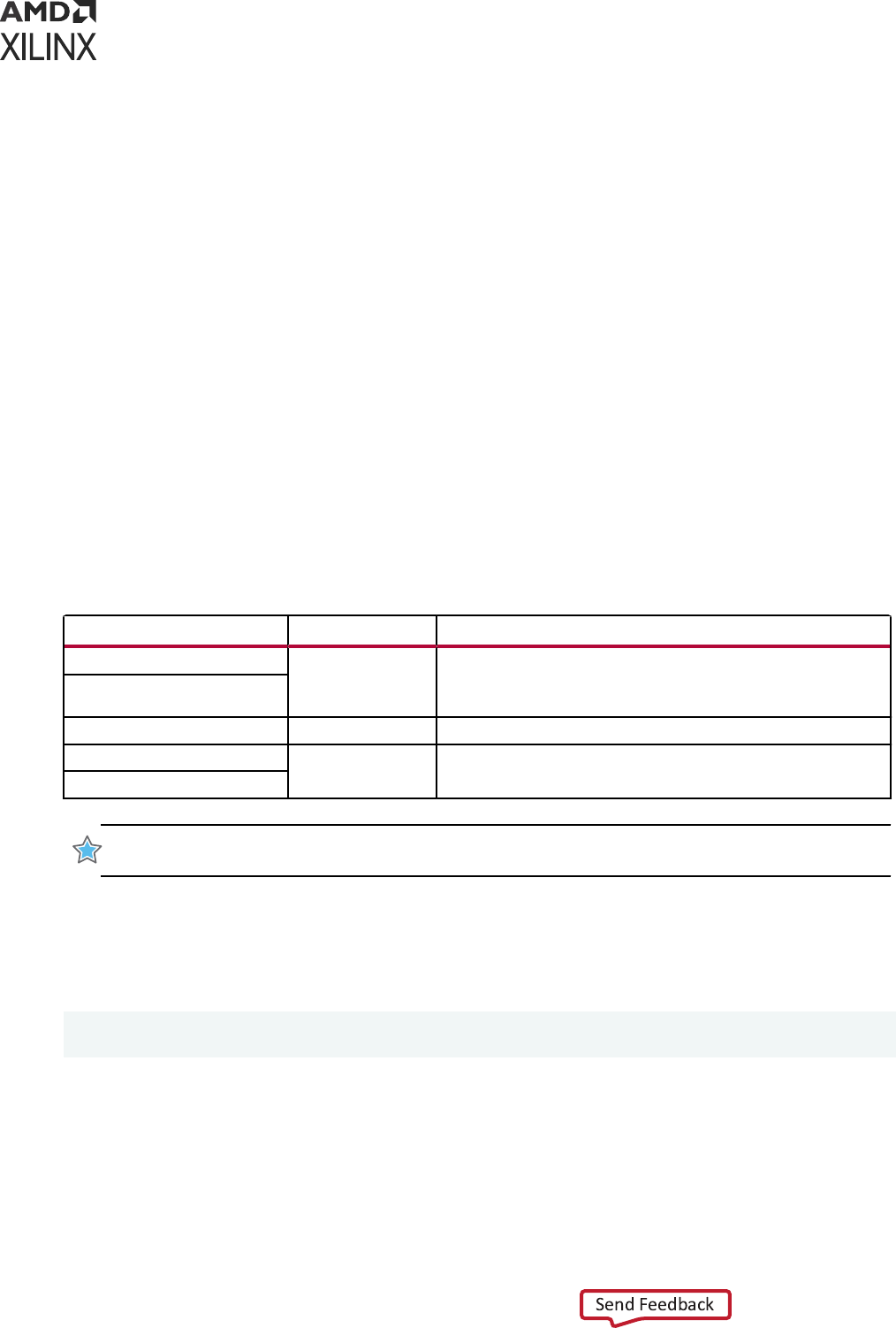
The following table illustrates the funcon of the simulator_language property.
Table 7: Function of simulator_language Property
IP Delivered Simulation Model simulator_language Value Simulation Model Used
IP delivers VHDL and Verilog behavioral
models
Mixed Behavioral model (target_language)
Verilog Verilog behavioral model
VHDL VHDL behavioral model
IP delivers Verilog behavioral model
only
Mixed Verilog behavioral model
Verilog Verilog behavioral model
VHDL VHDL simulation netlist generated from DCP
IP delivers VHDL behavioral model only Mixed VHDL behavioral model
Verilog Verilog simulation netlist generated from
DCP
VHDL VHDL behavioral model
Chapter 2: Preparing for Simulation
UG900 (v2022.1) April 21, 2022 www.xilinx.com
Vivado Design Suite User Guide: Logic Simulation 31
Table 7: Function of simulator_language Property (cont'd)
IP Delivered Simulation Model simulator_language Value Simulation Model Used
IP delivers no behavioral models Mixed, Verilog, VHDL Netlist generated from DCP
(target_language)
Notes:
1. Where available, behavioral simulation models always take precedence over structural simulation models. The Vivado
tools select behavioral or structural models automatically, based on model availability. It is not possible to override
the automated selection.
2. Use the target_language property when either language can be used for simulation Tcl: set_property
target_language VHDL [current_project]
3. Setting VHDL as a target language for Versal
®
devices is not yet supported. This will result in an error in simulation.
Setting the Simulation Runtime Resolution
Set the simulaon run-me resoluon using `timescale in test bench. There is no simulator
performance gain achieved through use of coarser resoluon with the Xilinx simulaon models.
(In Xilinx simulaon models, most simulaon me is spent in delta cycles, and delta cycles are not
aected by simulator resoluon.)
IMPORTANT! Run simulaons using a me resoluon of 1 fs. Some Xilinx primive components, such as
GT, require a 1 fs resoluon to work properly in either funconal or ming simulaon.
See Simulaon Opons for detailed informaon on Simulaon Opons in Sengs dialog box.
IMPORTANT!
Picoseconds are used as the minimum resoluon because tesng equipment can measure
ming only to the nearest picosecond resoluon.
Adding or Creating Simulation Source Files
To add simulaon sources to a Vivado Design Suite project:
1. Select File → Add Sources, or click Add Sources in the Flow Navigator.
The Add Sources wizard opens.
2. Select Add or Create Simulaon Sources, and click Next.
The Add or Create Simulaon Sources dialog box opens. The opons are:
• Add Files: Invokes a le browser so you can select simulaon source les to add to the
project.
• Add Directories: Invokes directory browser to add all simulaon source les from the
selected directories. Files in the specied directory with valid source le extensions are
added to the project.
Chapter 2: Preparing for Simulation
UG900 (v2022.1) April 21, 2022 www.xilinx.com
Vivado Design Suite User Guide: Logic Simulation 32

• Create File: Invokes the Create Source File dialog box where you can create new
simulaon source les. See this link in the Vivado Design Suite User Guide: System-Level
Design Entry (UG895) for more informaon about project source les.
• Buons on the side of the dialog box let you do the following:
○ Remove : Removes the selected source les from the list of les to be added.
○ Move Up : Moves the le up in the list order.
○
Move Down
: Moves the le down in the list order.
• Check boxes in the wizard provide the following opons:
○
- Scan and add RTL include les into project: Scans the added RTL le and adds any
referenced include les.
- Copy sources into project: Copies the original source les into the project and uses
the local copied version of the le in the project.
If you elected to add directories of source les using the Add Directories command, the
directory structure is maintained when the les are copied locally into the project.
- Add sources from subdirectories: Adds source les from the subdirectories of
directories specied in the Add Directories opon.
- Include all design sources for simulaon: Includes all the design sources for
simulaon.
VIDEO: For a demonstraon of this feature, see the Vivado Design Suite QuickTake Video: Logic
Simulaon.
Working with Simulation Sets
The Vivado IDE stores simulaon source les in simulaon sets that display in folders in the
Sources window, and are either remotely referenced or stored in the local project directory.
The simulaon set lets you dene dierent sources for dierent stages of the design. For
example, there can be one test bench source to provide smulus for behavioral simulaon of the
elaborated design or a module of the design, and a dierent test bench to provide smulus for
ming simulaon of the implemented design.
When adding simulaon sources to the project, you can specify which simulaon source set to
use.
To edit a simulaon set:
1. In the Sources window popup menu, right click Simulaon Sources and click Edit Simulaon
Sets, as shown in the following gure.
Chapter 2: Preparing for Simulation
UG900 (v2022.1) April 21, 2022 www.xilinx.com
Vivado Design Suite User Guide: Logic Simulation 33
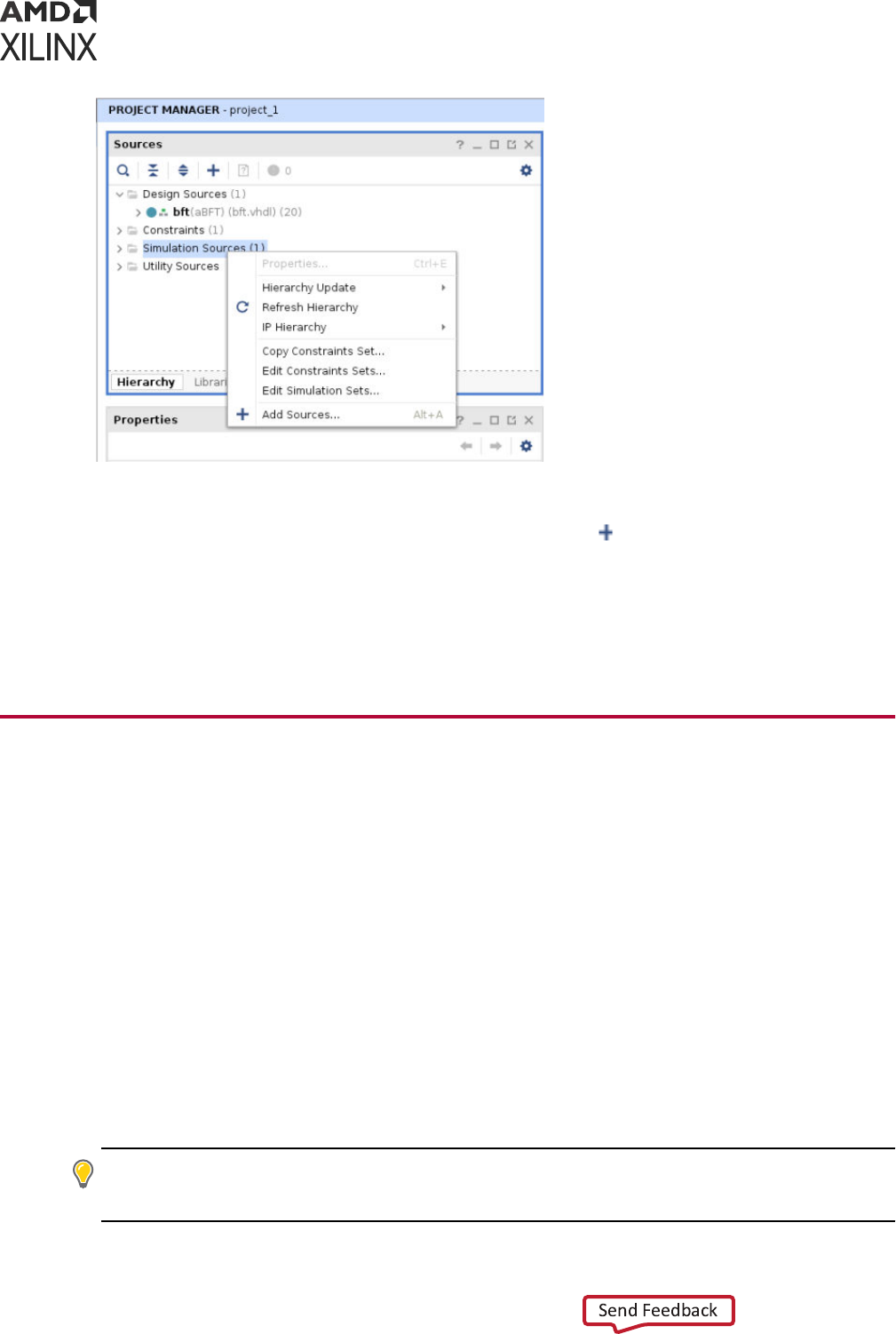
The Add or Create Simulaon Sources wizard opens.
2. From the Add or Create Simulaon Sources wizard, select
Add Sources.
This adds the sources associated with the project to the newly-created simulaon set.
3. Add addional les as needed.
The selected simulaon set is used for the acve design run.
Generating a Netlist
To run simulaon of a synthesized or implemented design run the netlist generaon process. The
netlist generaon Tcl commands can take a synthesized or implemented design database and
write out a single netlist for the enre design.
The Vivado Design Suite generates a netlist automacally when you launch the simulator using
the IDE or the launch_simulation command.
Netlist generaon Tcl commands can write SDF and the design netlist. The Vivado Design Suite
provides the following Tcl commands:
• write_verilog: Verilog netlist
• write_vhdl: VHDL netlist
• write_sdf: SDF generaon
TIP:
The SDF values are only esmates early in the design process (for example, during synthesis). As the
design process progresses, the accuracy of the ming numbers also progress when there is more
informaon available in the database.
Chapter 2: Preparing for Simulation
UG900 (v2022.1) April 21, 2022 www.xilinx.com
Vivado Design Suite User Guide: Logic Simulation 34

Generating a Functional Netlist
The Vivado Design Suite supports wring out a Verilog or VHDL structural netlist for funconal
simulaon. The purpose of this netlist is to run simulaon (without ming) to check that the
behavior of the structural netlist matches the expected behavioral model (RTL) simulaon.
The funconal simulaon netlist is a hierarchical, folded netlist that is expanded to the primive
module or enty level; the lowest level of hierarchy consists of primives and macro primives.
These primives are contained in the following libraries:
• UNISIMS_VER simulaon library for Verilog simulaon
• UNISIMS simulaon library for VHDL simulaon
In many cases, you can use the same test bench that you used for behavioral simulaon to
perform a more accurate simulaon.
The following Tcl commands generate Verilog and VHDL funconal simulaon netlist,
respecvely:
write_verilog -mode funcsim <Verilog_Netlist_Name.v>
write_vhdl -mode funcsim <VHDL_Netlist_Name.vhd>
Generating a Timing Netlist
You can use a Verilog ming simulaon to verify circuit operaon aer the Vivado tools have
calculated the worst-case placed and routed delays.
In many cases, you can use the same test bench that you used for funconal simulaon to
perform a more accurate simulaon.
Compare the results from the two simulaons to verify that your design is performing as inially
specied.
There are two steps to generang a ming simulaon netlist:
1. Generate a simulaon netlist le for the design.
2. Generate an SDF delay le with all the ming delays annotated.
IMPORTANT! Vivado IDE supports Verilog ming simulaon only.
TIP: If you are a VHDL user, you can run post-synthesis and post-implementaon funconal
simulaon (in which case no standard default format (SDF) annotaon is required and the simulaon
netlist uses the UNISIM library). You can create the netlist using the write_vhdl Tcl command. For
usage informaon, see the Vivado Design Suite Tcl Command Reference Guide (UG835).
Chapter 2: Preparing for Simulation
UG900 (v2022.1) April 21, 2022 www.xilinx.com
Vivado Design Suite User Guide: Logic Simulation 35

The following is the Tcl syntax for generang a ming simulaon netlist:
write_verilog -mode timesim -sdf_anno true <Verilog_Netlist_Name>
Using Versal CIPS VIP
The Versal
®
ACAP Control, Interfaces, and Processing System (CIPS) Vericaon Intellectual
Property (VIP) supports the funconal simulaon of Versal ACAP applicaons. It is targeted to
enable the funconal vericaon of the programmable logic (PL) by mimicking the processor
system (PS)-PL interfaces and OCM memories of the PS logic. This VIP is delivered as a package
of System Verilog modules. The VIP operaon is controlled by using a sequence of System
Verilog tasks. This is supported in the latest version of Vivado. For more informaon, see Versal
ACAP CIPS Vericaon IP Data Sheet (DS996).
Chapter 2: Preparing for Simulation
UG900 (v2022.1) April 21, 2022 www.xilinx.com
Vivado Design Suite User Guide: Logic Simulation 36
Chapter 3
Simulating with Third-Party
Simulators
The Vivado
®
Design Suite supports simulaon using third-party tools. Simulaon with third-party
tools can be performed directly from within the Vivado Integrated Design Environment (IDE) or
using a custom external simulaon environment.
Table 8: Supported Third-Party Simulators
Third-party Simulators Red Hat 64-bit Linux Windows 10 64-bit
Siemens EDA ModelSim SE Yes Yes
Siemens EDA Questa Advanced Simulator Yes Yes
Cadence Xcelium Parallel Simulator Yes NA
Synopsys VCS Yes NA
Aldec Active HDL NA Yes
Aldec Riviera PRO Yes Yes
The Vivado Design Suite User Guide: Using the Vivado IDE (UG893) describes the use of the Vivado
IDE.
Please set the following environment variables before running simulaon in Vivado IDE.
Table 9: Environment Variable Setting for Third-Party Simulators
Simulator Linux Windows
Modelsim
setenv MODEL_TECH <tool installation path>
setenv LM_LICENSE_FILE <license file>
setenv PATH ${MODEL_TECH}/bin:$PATH
set MODEL_TECH=<tool
installation path>
set LM_LICENSE_FILE=<license
file>
set Path=%MODEL_TECH%
\win32;%Path%
Questa
setenv MODEL_TECH <tool installation path>
setenv LM_LICENSE_FILE <license file>
setenv PATH ${MODEL_TECH}/bin:$PATH
set MODEL_TECH=<tool
installation path>
set LM_LICENSE_FILE=<license
file>
set Path=%MODEL_TECH%
\win32;%Path%
Chapter 3: Simulating with Third-Party Simulators
UG900 (v2022.1) April 21, 2022 www.xilinx.com
Vivado Design Suite User Guide: Logic Simulation 37
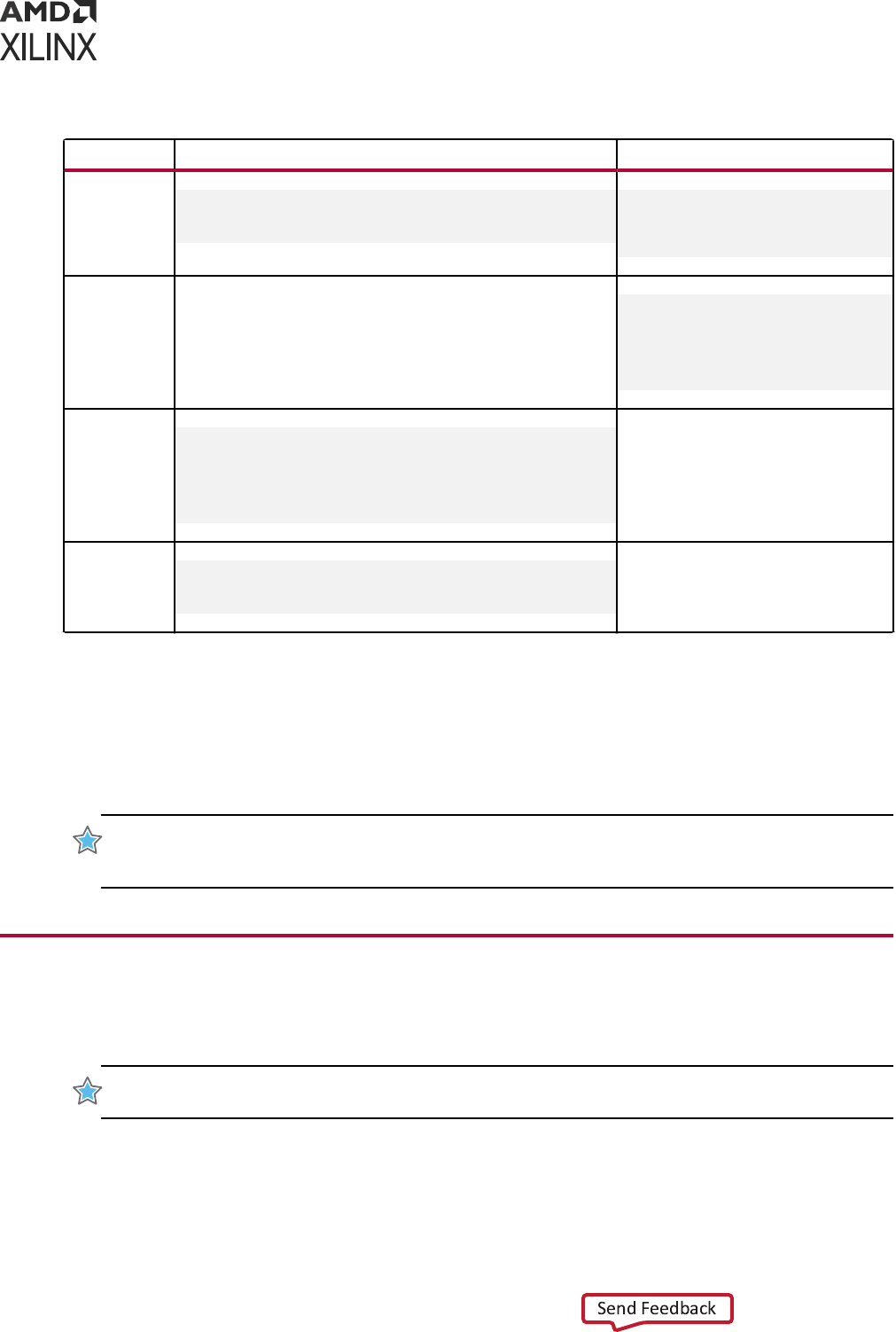
Table 9: Environment Variable Setting for Third-Party Simulators (cont'd)
Simulator Linux Windows
Riviera
In BASH
source <install_path>/etc/setenv
source <install_path>/etc/setgcc
call <install_path>/etc/
setenv.bat
call <install_path>/etc/
setgcc.bat
Active-HDL
NA
set ACTIVE_BIN=<tool
installation path>
set Path=%<Active_hdl install
dir>%\BIN;%Path%
set LM_LICENSE_FILE=<license
file>
Xcelium
setenv CDS_INST_DIR <xcelium_install_dir>
setenv LD_LIBRARY_PATH $CDS_INST_DIR/tools/
xcelium/lib:$LD_LIBRARY_PATH
setenv PATH $CDS_INST_DIR/tools/xcelium/
bin:$CDS_INST_DIR/tools/bin:$PATH
setenv CDS_LICENSE_DIR <tool_license>
NA
VCS
setenv VCS_HOME <tool_install_path>
setenv LM_LICENSE_FILE <license_file_path>
setenv PATH ${VCS_HOME}/bin:${PATH}
NA
Notes:
1. Tool installation path should be added to environment variable PATH (irrespective of OS). To simulate SystemC based
designs for the supported simulator, provide the required g++ version installation path as mentioned in Appendix F:
SystemC Support in Vivado IDE. The LD_LIBRARY_PATH should also include simulator library path.
For links to more informaon on your third party simulator, see Links to Addional Informaon
on Third-Party Simulators.
IMPORTANT!
Use only supported versions of third-party simulators. For more informaon on supported
Simulators and Operang Systems, see the Compable Third-Party Tools table in the Vivado Design Suite
User Guide: Release Notes, Installaon, and Licensing (UG973).
Running Simulation Using Third Party
Simulators with Vivado IDE
IMPORTANT!
Conrm the compiled library locaon (the path at which
compile_simlib
was invoked
or the one you specied with the
-directory
opon) before running a third-party simulaon.
From the Vivado IDE, you can compile, elaborate, and simulate the design based on the
simulaon sengs and launch the simulator in a separate window.
Chapter 3: Simulating with Third-Party Simulators
UG900 (v2022.1) April 21, 2022 www.xilinx.com
Vivado Design Suite User Guide: Logic Simulation 38
When you run simulaon prior to synthesizing the design, the simulator runs a behavioral
simulaon. Following each successful design step (synthesis and implementaon), the opon to
run a funconal or ming simulaon becomes available. You can iniate a simulaon run from
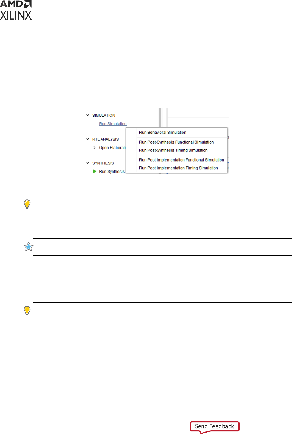
the Flow Navigator or by typing in a Tcl command.
From the Flow Navigator, click Run Simulaon, and select the type of simulaon you want to run,
as shown in the following gure:
Figure 5: Types of Simulation
To use the corresponding Tcl command, type: launch_simulation
TIP:
This command provides a
-scripts_only
opon that can be used to write a DO or SH le,
depending on the target simulator. Use the DO or SH le to run simulaons outside the IDE.
Note: If you are running VCS simulator outside of Vivado, make sure to use -full64 switch. Otherwise,
the simulator will not run if the design contains Xilinx IP.
IMPORTANT!
Use the following command to run the 32-bit Simulator:
set_property 32bit 1
[current_fileset -simset]
Note: Xilinx Vericaon IP (VIP) uses SystemVerilog construct. If you are using any IP which instanates
VIP, make sure that your simulator supports SystemVerilog.
Running Timing Simulation Using Third-Party Tools
TIP:
Post-Synthesis ming simulaon uses the esmated ming delay from the synthesized netlist. Post-
Implementaon ming simulaon uses actual ming delays.
When you run Post-Synthesis and Post-Implementaon ming simulaon, the simulators include:
• Gate-level netlist containing SIMPRIMS library components
• SECUREIP
• Standard Delay Format (SDF) les
You dene the overall design funconality in the beginning. When the design is implemented,
accurate ming informaon is available.
Chapter 3: Simulating with Third-Party Simulators
UG900 (v2022.1) April 21, 2022 www.xilinx.com
Vivado Design Suite User Guide: Logic Simulation 39

To create the netlist and SDF, the Vivado Design Suite:
• Calls the netlist writer, write_verilog with the -mode timesim switch and write_sdf
(SDF annotator)
• Sends the generated netlist to the target simulator
You control these opons using Simulaon Sengs as described in Using Simulaon Sengs.
IMPORTANT! Post-Synthesis and Post-Implementaon ming simulaons are supported for Verilog only.
There is no support for VHDL ming simulaon. If you are a VHDL user, you can run post-synthesis and
post-implementaon funconal simulaon (in which case no SDF annotaon is required and the
simulaon netlist uses the UNISIM library). You can create the netlist using the
write_vhdl
Tcl
command. For usage informaon, refer to the Vivado Design Suite Tcl Command Reference Guide
(UG835).
Post-Synthesis Timing Simulation
When synthesis runs successfully, the Run Simulaon → Post-Synthesis Timing Simulaon
opon becomes available.
Aer you select a post-synthesis ming simulaon, the ming netlist and the SDF le are
generated. The netlist les includes $sdf_annotate command so that the generated SDF le is
picked up.
Post-Implementation Timing Simulations
When post-implementaon is successful, the Run Simulaon → Post-Implementaon Timing
Simulaon opon becomes available.
Aer you select a post-implementaon ming simulaon, the ming netlist and the SDF le are
generated. The netlist les includes $sdf_annotate command so that the generated SDF le is
picked up.
Annotating the SDF File for Timing Simulation
When you specied simulaon sengs, you specied whether or not to create an SDF le and
whether the process corner would be set to fast or slow.
TIP:
To nd the SDF le opons sengs, in the Vivado IDE Flow Navigator, right-click Simulaon and
select Simulaon Sengs. In the Sengs dialog box, select Simulaon category and click Netlist tab.
Based on the specied process corner, the SDF le contains dierent min and max numbers.
RECOMMENDED:
To run a setup check, create an SDF le with -process_corner slow, and use the max
column from the SDF le.
Chapter 3: Simulating with Third-Party Simulators
UG900 (v2022.1) April 21, 2022 www.xilinx.com
Vivado Design Suite User Guide: Logic Simulation 40

To run a hold check, create an SDF le with the -process_corner fast, and use the min column
from the SDF le. The method for specifying which SDF delay eld to use is dependent on the
simulaon tool you are using. Refer to the specic simulaon tool documentaon for informaon
on how to set this opon.
To get full coverage run all four ming simulaons, specify as follows:
1. Slow corner: SDFMIN and SDFMAX
2. Fast corner: SDFMIN and SDFMAX
Running Standalone Timing Simulation
If you are running ming simulaon from Vivado IDE, it will add the ming simulaon related
switches to simulator. If you run standalone ming simulaon, make sure to pass the following
switch to simulators during elaboraon:
For VCS:
+pulse_e/<number> and +pulse_r/<number> +transport_int_delays
During elaboraon (with VCS)
For ModelSim/Questa Advanced Simulator:
+transport_int_delays +pulse_int_e/0 +pulse_int_r/0
During elaboraon (with vsim)
IMPORTANT!
The Vivado simulator models use interconnect delays; consequently, addional switches
are required for proper ming simulaon, as follows:
-transport_int_delays -pulse_r 0 -
pulse_int_r 0
. Table 15: xelab, xvhd, and xvlog Command Opons provides descripons for the these
commands.
Dumping SAIF for Power Analysis
The Switching Acvity Interchange Format (SAIF) is an ASCII report that assists in extracng and
storing switching acvity informaon generated by simulator tools. This switching acvity can be
back-annotated into the Xilinx power analysis and opmizaon tools for the power
measurements and esmaons.
Chapter 3: Simulating with Third-Party Simulators
UG900 (v2022.1) April 21, 2022 www.xilinx.com
Vivado Design Suite User Guide: Logic Simulation 41

Dumping SAIF in Questa Advanced Simulator/
ModelSim
Questa Advanced Simulator/ModelSim uses explicit power commands to dump an SAIF le, as
follows:
1. Specify the scope or signals to dump, by typing:
power add <hdl_objects>
2. Run simulaon for specic me (or run -all).
3. Dump out the power report, by typing:
power report -all filename.saif
For more detailed usage or informaon about each commands, see the ModelSim
documentaon.
Example DO File
power add tb/fpga/*
run 500us
power report -all -bsaif routed.saif
quit
Dumping SAIF in VCS
VCS provides power commands to generate SAIF with specic requirements.
1. Specify the scope and signals to be generated, by typing:
power <hdl_objects>
2. Enable SAIF dumping. You can use the command line in the simulator workspace:
power -enable
3. Run simulaon for a specic me.
4. Disable power dumping and report the SAIF, by typing:
power -disable
power -report filename.saif
For more detailed usage or informaon about each command, see the Synopsys VCS
documentaon.
See Power Analysis Using Vivado Simulator for more informaon about Switching Acvity
Interchange Format (SAIF).
Chapter 3: Simulating with Third-Party Simulators
UG900 (v2022.1) April 21, 2022 www.xilinx.com
Vivado Design Suite User Guide: Logic Simulation 42

Dumping VCD
You can use a Value Change Dump (VCD) le to capture simulaon output. The Tcl commands
are based on Verilog system tasks related to dumping values.
Dumping VCD in Questa Advanced Simulator/
ModelSim
Questa Advanced Simulator/ModelSim uses explicit VCD commands to dump a VCS le, as
follows:
1. Open the VCD le:
vcd file my_vcdfile.vcd
2. Specify the scope or signals to dump:
vcd add <hdl_objects>
3. Run simulaon for a specied period of me (or run -all).
For more detailed usage or informaon about each commands, see the ModelSim
documentaon.
Example DO File:
vcd file my_vcdfile.vcd
vcd add -r tb/fpga/*
run 500us
quit
Dumping VCD in VCS
In VCS, you can generate a VCD le using the dumpvar command. Specify the le name and
instance name (by default its complete hierarchy).
vcs +vcs+dumpvars+test.vcd
Chapter 3: Simulating with Third-Party Simulators
UG900 (v2022.1) April 21, 2022 www.xilinx.com
Vivado Design Suite User Guide: Logic Simulation 43

Simulating IP
In the following example, the accum_0.xci le is the IP you generated from the Vivado
®
IP
catalog. Use the following commands to simulate this IP in VCS:
set_property target_simulator VCS [current_project]
set_property compxlib.vcs_compiled_library_dir
<compiled_library_location>[current_project]
launch_simulation -noclean_dir -of_objects [get_files accum_0.xci]
Using a Custom DO File During an Integrated
Simulation Run
If you have some specic set of commands (custom DO le) that you want to invoke just before
running the simulaon, add those commands in a le and pass that using the appropriate
command, as shown below:
In Questa Advanced Simulator
expanse="page">set_property -name {questa.simulate.tcl.post} -value
{<AbsolutePathOfFileLocation>}
-objects [get_filesets sim_1]
In Modelsim
expanse="page">set_property -name {modelsim.simulate.tcl.post} -value
{<AbsolutePathOfFileLocation>}
-objects [get_filesets sim_1]
In VCS
expanse="page">set_property -name {vcs.simulate.tcl.post} -value
{<AbsolutePathOfFileLocation>} -objects
[get_filesets sim_1]
In Xcelium
expanse="page">set_property -name {xcelium.simulate.tcl.post} -value
{<AbsolutePathOfFileLocation>}
-objects
expanse="page">[get_filesets sim_1]
Chapter 3: Simulating with Third-Party Simulators
UG900 (v2022.1) April 21, 2022 www.xilinx.com
Vivado Design Suite User Guide: Logic Simulation 44
Simulation Step Control Constructs for ModelSim
and Questa Advanced Simulator
The following table outlines the constructs used for controlling the step execuon based on the
do le format:
• Nave do le: This is a default do le format. In this format, the compile and elaborate shell
scripts calls source <tb>_compile/elaborate.do. For example:
source bft_tb_compile.do 2>&1 | tee -a compile.log
The simulate script calls vsim -64 -c -do do {<tb>_simulate.do}. For example:
$bin_path/vsim -64 -c -do do {bft_tb_simulate.do} -l simulate.log
• Classic do le: Classic do le format is dierent from the nave do le in compile and
elaborate shell scripts. There is no change in the simulate script. In compile and elaborate shell
scripts, it calls vsim -c -do do {<tb>_compile/elaborate.do}. For example,
$bin_path/vsim -64 -c -do do {bft_tb_compile.do} -l compile.log
To get this, set project.writeNativeScriptForUnifiedSimulation to 0 by invoking
set_param project.writeNativeScriptForUnifiedSimulation 0 on Tcl console
command.
This le format is useful for a shared project as the path for Questa Advanced Simulator/
ModelSim ulity is hard-coded inside the shell scripts.
Table 10: Simulation Step Control Construct Parameters
Parameter Description Default
project.writeNativeScriptForUnifiedSimulatio
n
Write a pure .do file with simulator command
only (no Tcl or Shell constructs).
0 (false)
simulator.quitOnSimulationComplete
Quit simulator on simulator completion for
ModelSim/Questa Advanced Simulator
simulation. To disable quit, set this parameter
to false.
1 (true)
simulator.modelsimNoQuitOnError
Do not quit on error or break by default for
ModelSim/Questa Advanced Simulator
simulation. To quit simulation on error or
break, set this parameter to false.
1 (true)
Explanation
• simulator.quitOnSimulationComplete: By default, the generated simulate.do has
quit -force. When the simulaon is complete in the specied me, the simulator exits. If
you do not want the simulator to exit, set simulator.quitOnSimulationComplete to 0
by invoking set_peram simulator.quitOnSimulationComplete 0.
Chapter 3: Simulating with Third-Party Simulators
UG900 (v2022.1) April 21, 2022 www.xilinx.com
Vivado Design Suite User Guide: Logic Simulation 45

• simulator.modelsimNoQuitOnError: By default, on error or break, simulator does not
exit. If you want to exit the simulator, set the following parameter:
set_param simulator.modelsimNoQuitOnError 0
This adds the following two lines in <tb>_simulate.do.
onbreak {quit -f}
onerror {quit -f}
Running Third-Party Simulators in Batch
Mode
The Vivado Design Suite supports batch or scripted simulaon for third party vericaon. With
the design les gathered, and the scripts generated to support your target simulator, you can
inspect the scripts and incorporate them into your vericaon environment. Xilinx recommends
that you use the export_simulation scripts as a starng point for your simulaon ow rather
than building a custom API to generate scripts. See Exporng Simulaon Files and Scripts for
more informaon on exporng simulaon scripts.
Make sure that you have the correct environment setup for the simulator before running the
scripts. See Using Simulaon Sengs for more informaon on conguring your simulator. See
the User Guide of your specic simulator for the details of running batch or scripted mode.
Chapter 3: Simulating with Third-Party Simulators
UG900 (v2022.1) April 21, 2022 www.xilinx.com
Vivado Design Suite User Guide: Logic Simulation 46

Chapter 4
Simulating with Vivado Simulator
The Vivado simulator is a Hardware Descripon Language (HDL) event-driven simulator that
supports funconal and ming simulaons for VHDL, Verilog, SystemVerilog (SV), and mixed
VHDL/Verilog or VHDL/SV designs.
The Vivado simulator supports the following features:
• Source code debugging (step, breakpoint, current value display)
• SDF annotaon for ming simulaon
• VCD dumping
• SAIF dumping for power analysis and opmizaon
• Nave support for HardIP blocks (such as serial transceivers and PCIe
®
)
• Mul-threaded compilaon
• Mixed language (VHDL, Verilog, or SystemVerilog design constructs)
• Single-click simulaon re-compile and re-launch
• One-click compilaon and simulaon
• Built-in support for Xilinx simulaon libraries
• Real-me waveform update
See the Vivado Design Suite Tutorial: Logic Simulaon (UG937) for a step-by-step demonstraon of
how to run Vivado simulaon.
Running the Vivado Simulator
IMPORTANT!
If you are using the Vivado simulator, be sure to specify all appropriate project sengs for
your design before running simulaon. For supported third-party simulators, see Chapter 3: Simulang
with Third-Party Simulators.
From the Flow Navigator, click Run Simulaon and select a simulaon type to invoke the Vivado
simulator workspace, shown in the gure below.
Chapter 4: Simulating with Vivado Simulator
UG900 (v2022.1) April 21, 2022 www.xilinx.com
Vivado Design Suite User Guide: Logic Simulation 47
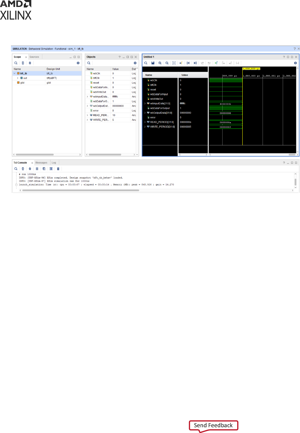
Figure 6: Vivado Simulator Workspace
Main Toolbar
The main toolbar provides one-click access to the most commonly used commands in the Vivado
IDE. When you hover over an opon, a tool p appears that provides more informaon.
Run Menu
The menus provide the same opons as the Vivado IDE with the addion of a Run menu aer
you have run a simulaon.
The Run menu for simulaon is shown in the following gure.
Chapter 4: Simulating with Vivado Simulator
UG900 (v2022.1) April 21, 2022 www.xilinx.com
Vivado Design Suite User Guide: Logic Simulation 48
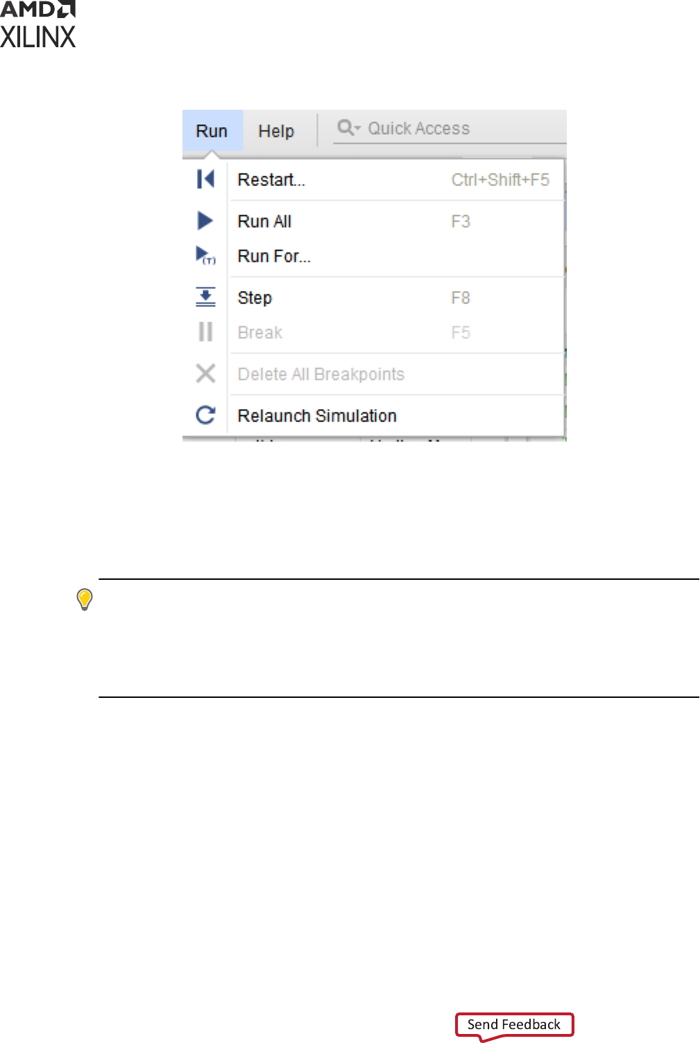
Figure 7: Simulation Run Menu Options
The Vivado simulator Run menu opons:
• Restart: Lets you restart an exisng simulaon from me 0. Tcl Command: restart
• Run All: Lets you run an open simulaon to compleon. Tcl Command: run -all
• Run For: Lets you specify a me for the simulaon to run. Tcl Command: run <time>
TIP: While you can always specify me units in the run command such as
run 100 ns
, you can also
omit the me unit. If you omit the me unit, the Vivado simulator will assume the me unit of the
TIME_UNIT Tcl property. To view the TIME_UNIT property use the Tcl command
get_property
time_unit [current_sim]
. To change the TIME_UNIT property use the Tcl command
set_property time_unit <unit> [current_sim]
, where <unit> is one of the following:
fs, ps, ns, us, ms, and s.
• Step: Runs the simulaon up to the next HDL source line.
• Break: Lets you pause a running simulaon.
• Delete All Breakpoints: Deletes all breakpoints.
• Relaunch Simulaon: Recompiles the simulaon les and restarts the simulaon.
Related Information
Re-running the Simulaon Aer Design Changes (relaunch)
Chapter 4: Simulating with Vivado Simulator
UG900 (v2022.1) April 21, 2022 www.xilinx.com
Vivado Design Suite User Guide: Logic Simulation 49

Simulation Toolbar
When you run the Vivado simulator, the simulaon-specic toolbar (shown in the gure below)
opens to the right of the main toolbar.
Figure 8: Simulation Toolbar
These are the same buons labeled in Run Menu, above (without the Delete All Breakpoints
opon), and they are provided for ease of use.
Simulation Toolbar Button Descriptions
Hover over the toolbar buons for tool-p descripons.
• Restart: resets the simulaon me to zero.
• Run all: runs the simulaon unl it completes all events or unl an HDL statement indicates
that the simulaon should stop.
• Run For: runs for a specied period of me.
• Step: runs the simulaon unl the next HDL statement.
• Break: Pauses the current simulaon.
• Relaunch: Recompiles the simulaon sources and restarts the simulaon (aer making code
changes, for example).
Related Information
Re-running the Simulaon Aer Design Changes (relaunch)
Sources Window
The Sources window displays the simulaon sources in a hierarchical tree, with views that show
Hierarchy, IP Sources, Libraries, and Compile Order, as shown in the following gure.
Chapter 4: Simulating with Vivado Simulator
UG900 (v2022.1) April 21, 2022 www.xilinx.com
Vivado Design Suite User Guide: Logic Simulation 50
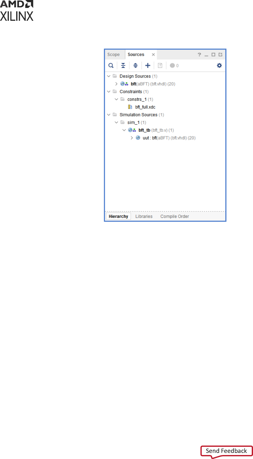
Figure 9: Sources Window
The Sources buons are described by tool ps when you hover the mouse over them. The
buons let you examine, expand, collapse, add to, open, lter and scroll through les.
You can also open or add a source le by right-clicking on the source object and selecng the
Open File or Add Sources opons.
Scope Window
A scope is a hierarchical paron of an HDL design. Whenever you instanate a design unit or
dene a process, block, package, or subprogram, you create a scope.
In the Scope window (shown in the gure below), you can see the design hierarchy. When you
select a scope in the Scope window, all HDL objects visible from that scope appear in the Objects
window. You can select HDL objects in the Objects window and add them to the waveform
viewer.
Chapter 4: Simulating with Vivado Simulator
UG900 (v2022.1) April 21, 2022 www.xilinx.com
Vivado Design Suite User Guide: Logic Simulation 51

Figure 10: Scope Window
Filtering Scopes
• Click Sengs opon on the scopes sub-menu to toggle between showing or hiding (check or
uncheck) the corresponding scope type.
TIP: When you hide a scope using Seng opon, all scopes inside that scope are also hidden regardless
of type. For example, in the gure above, clicking the Verilog Module buon to hide all Verilog module
scopes would hide not only the
bft_tb
scope but also
uut
(even though
uut
is a VHDL enty
scope).
• To limit the display to scopes containing a specied string, click the Search buon and
type the string in the text box.
The objects displayed in the Objects window change (or are ltered) based on the current scope.
Select the current scope to change the objects in the Objects window.
When you right-click a scope, a menu (shown in the following gure) appears with the following
opons:
Chapter 4: Simulating with Vivado Simulator
UG900 (v2022.1) April 21, 2022 www.xilinx.com
Vivado Design Suite User Guide: Logic Simulation 52
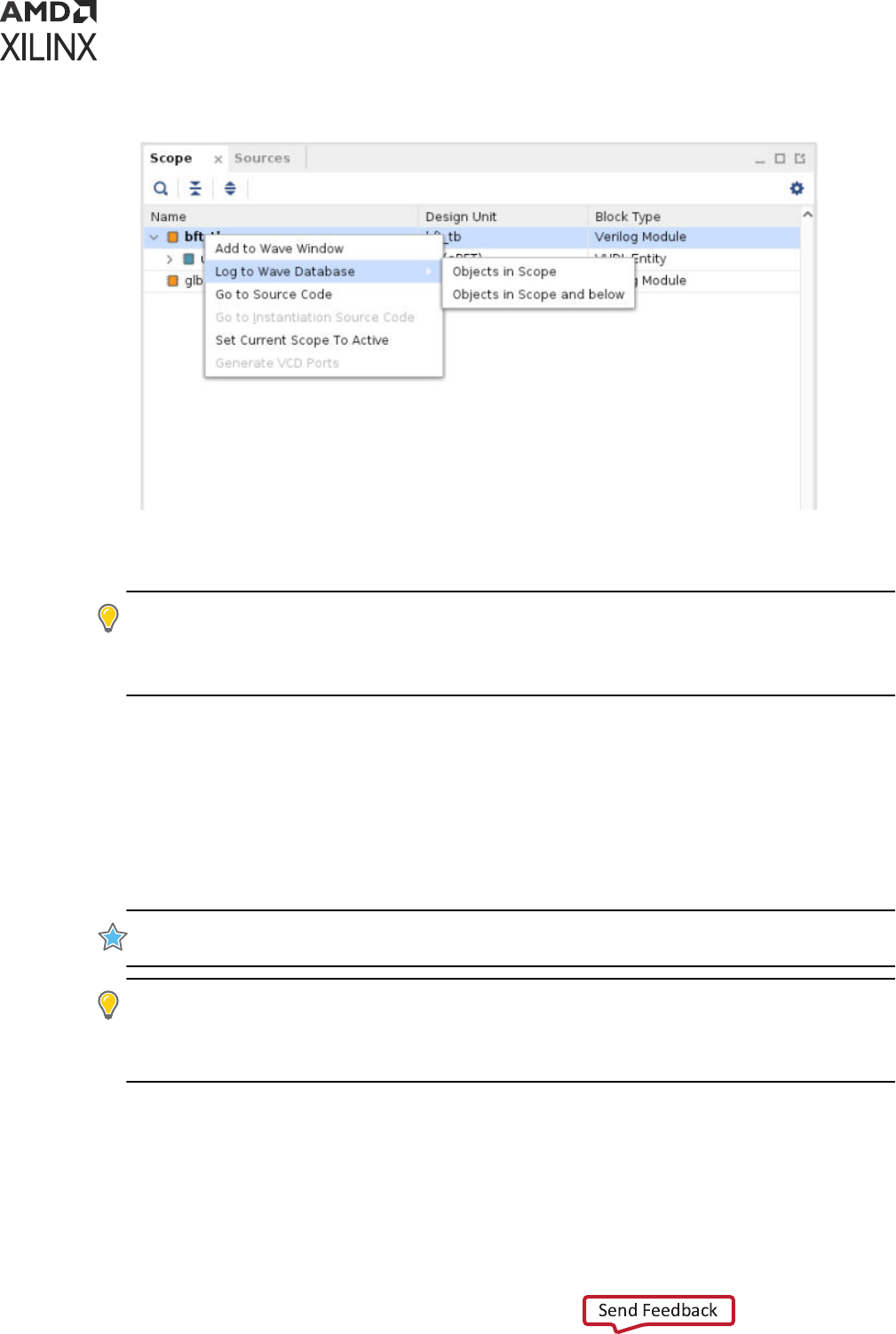
Figure 11: Scope Window Options
• Add to Wave Window: Adds all viewable HDL objects of the selected scope to the waveform
conguraon.
TIP: HDL objects of large bit width can slow down the display of the waveform viewer. You can lter
out such objects by seng a display limit on the wave conguraon before issuing the Add to Wave
Window command. To set a display limit, use the Tcl command
set_property DISPLAY_LIMIT
<maximum bit width> [current_wave_config]
.
The Add to Wave Window command might add a dierent set of HDL objects from the set
displayed in the Objects window. When you select a scope in the Scope window, the Objects
window might display HDL objects from enclosing scopes in addion to objects dened
directly in the selected scope. The Add to Wave Window command, on the other hand, adds
objects from the selected scope only.
Alternately, you can drag and drop items in the Objects window into the Name column of the
Wave window.
IMPORTANT! The Wave window displays the value changes of an object over me, starng from the
simulaon me at which the object was added.
TIP: To display object values prior to the me of inseron, the simulaon must be restarted. To avoid
having to restart the simulaon because of missing value changes: issue the
log_wave -r /
Tcl
command at the start of a simulaon run to capture value changes for all display-able HDL objects in
your design. For more informaon, see Using the log_wave Tcl Command.
Changes to the waveform conguraon, including creang the waveform conguraon or
adding HDL objects, do not become permanent unl you save the WCFG le.
• Go To Source Code: Opens the source code at the denion of the selected scope.
Chapter 4: Simulating with Vivado Simulator
UG900 (v2022.1) April 21, 2022 www.xilinx.com
Vivado Design Suite User Guide: Logic Simulation 53
• Go To Instanaon Source Code: For Verilog modules and VHDL enty instances, opens the
source code at the point of instanaon for the selected instance.
• Set Current Scope to Acve: Set the current scope to selected scope. The selected scope
becomes the acve simulaon scope (i.e. get_property active_scope
[current_sim]). Acve simulaon scope is the HDL process scope, where the simulaon is
currently paused. When used by disabling the follow acve scope in seng, Vivado simulator
will remember the last current_scope selecon even when simulaon proceeds. When a
break-point is hit, current_scope will sll point to last scope which is set as acve scope
• Log to Wave Database: You can log either of the following:
○ The objects of current scope
○ The objects of the current scope and all scope below the current scope.
TIP: By default, the Vivado simulator suppresses the logging of large HDL objects. To change the size
limit of logged objects, use the
set_property trace_limit <size> [current_sim]
Tcl
command, where
<size>
is the number of scalar elements in the HDL object.
In the source code text editor, you can hover over an idener in the code get the value, as
shown in Scope Window.
IMPORTANT! For this feature to work, be sure you have the scope associated with the source code
selected in the Scope window.
TIP: Because the top module is not instanated, the Go to Instanaon Source Code right-click opon
(shown in the gure above) is grayed out when the top module is selected.
TIP: Use
log_wave
to log the objects of current scope or below. Post simulaon, you can add any
objects on waveform and see the plot starng from me 0 ll current simulaon.
Chapter 4: Simulating with Vivado Simulator
UG900 (v2022.1) April 21, 2022 www.xilinx.com
Vivado Design Suite User Guide: Logic Simulation 54
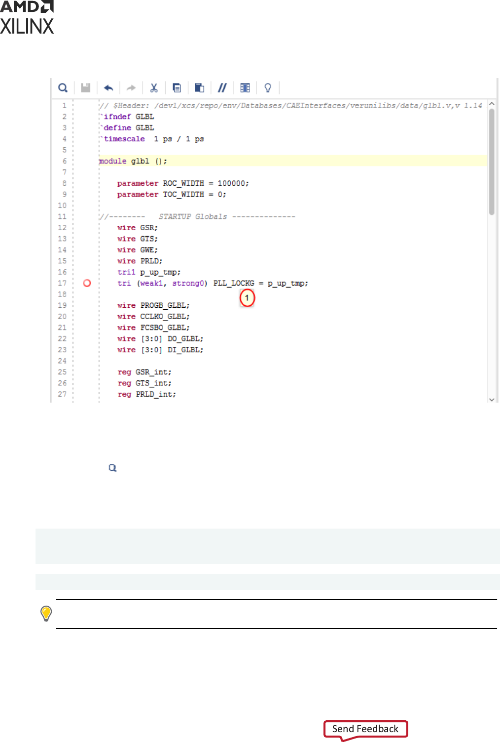
Figure 12: Source Code with Identifier Value Displayed
Additional Scopes and Sources Options
In either the Scope or the Sources window, a search eld displays when you select the Show
Search buon
.
As an equivalent to using the Scope and Objects windows, you can navigate the HDL design by
typing the following in the Tcl Console:
get_scopes
current_scope
report_scopes
id="ai516872">report_values
TIP:
To access source les for eding, you can open les from the Scope or Objects window by selecng Go
to Source Code, as shown in Scope Window.
Chapter 4: Simulating with Vivado Simulator
UG900 (v2022.1) April 21, 2022 www.xilinx.com
Vivado Design Suite User Guide: Logic Simulation 55
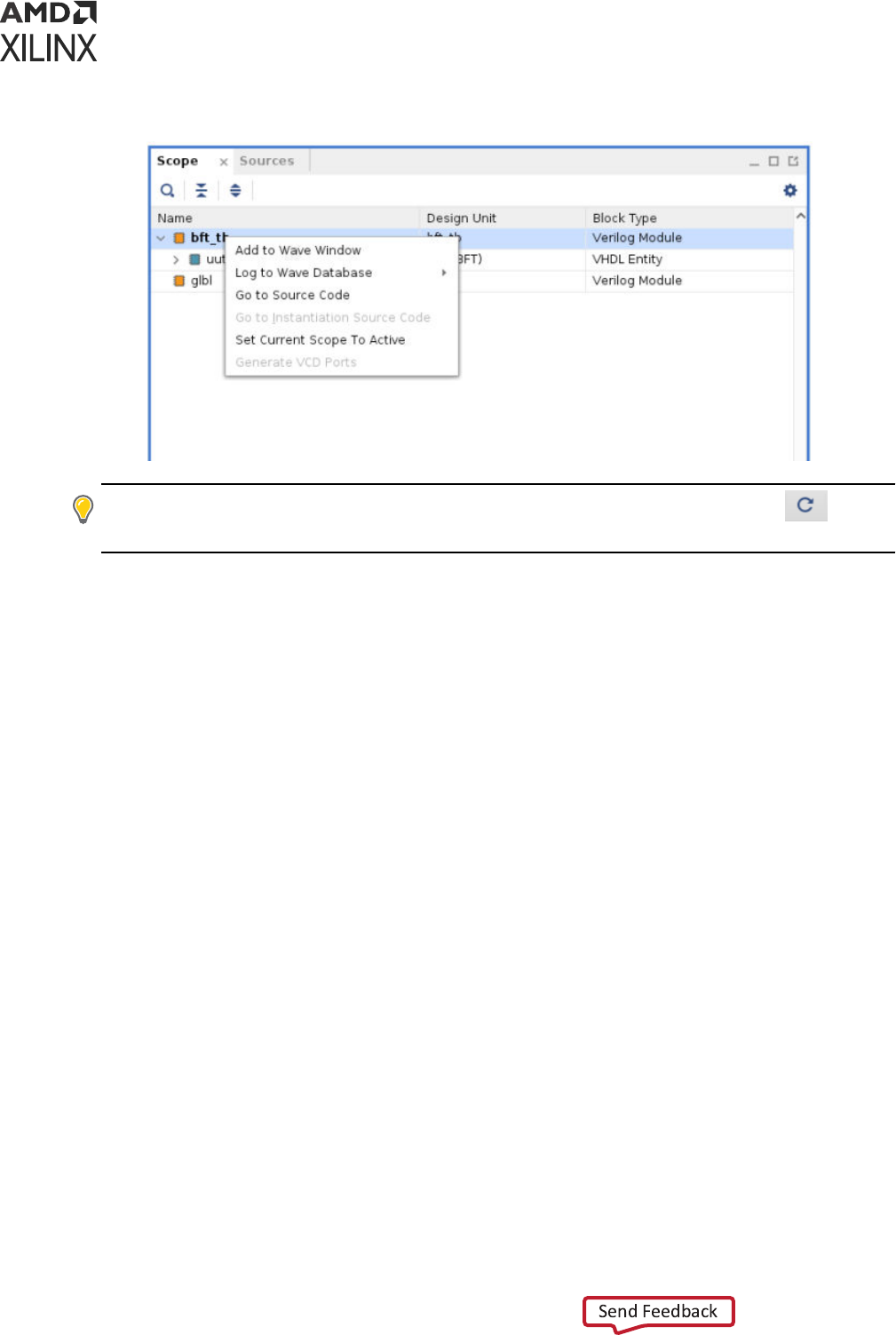
Figure 13: Context Menu in Scope Window
TIP: Aer you have edited source code and saved the le, you can click the Relaunch buon to
recompile and relaunch simulaon without having to close and reopen the simulaon.
Objects Window
The Objects window displays the HDL simulaon objects associated with the scope selected in
the Scope window, as shown in the following gure.
Chapter 4: Simulating with Vivado Simulator
UG900 (v2022.1) April 21, 2022 www.xilinx.com
Vivado Design Suite User Guide: Logic Simulation 56
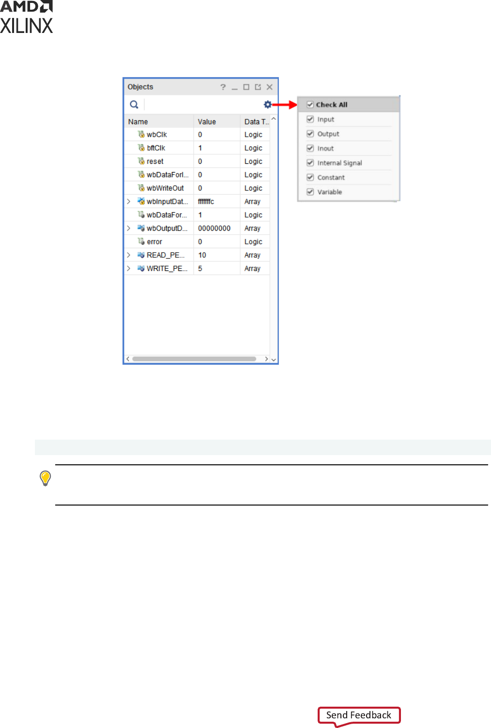
Figure 14: Objects Window
Icons beside the HDL objects show the type or port mode of each object. This view lists the
Name, Value, and Data Type of the simulaon objects.
You can obtain the current value of an object by typing the following in the Tcl Console.
get_value <hdl_object>
TIP:
To limit the number of digits to display for vectors, use the
set_property
array_display_limit <bits> [current_sim]
command, where <bits> is the number of bits
to display.
The following are the opons available at the top of the Objects window. Click Sengs to view
the selected objects in the Objects window. Use this to lter or limit the contents of the Objects
window.
• Search: You can use the Search opon to search for an object name.
• Sengs: Sengs opon allows you to display or hide various HDL objects in the Objects
window.
Chapter 4: Simulating with Vivado Simulator
UG900 (v2022.1) April 21, 2022 www.xilinx.com
Vivado Design Suite User Guide: Logic Simulation 57
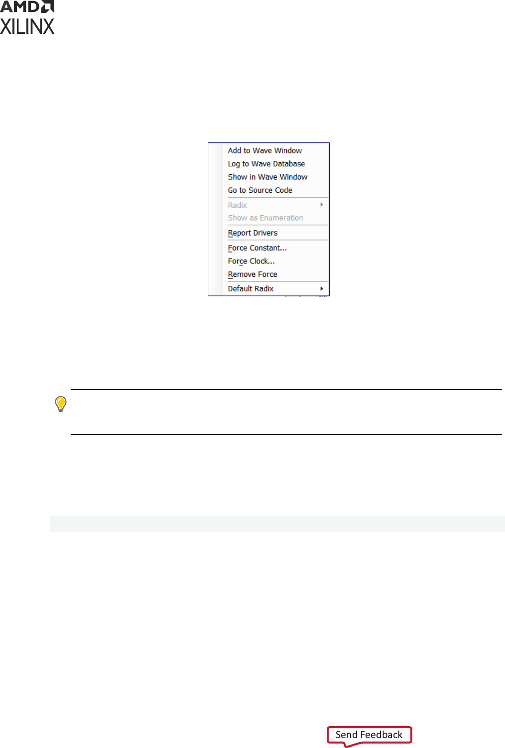
Objects Context Menu
When you right-click an object in the Objects window, a context menu (shown in Objects
Window) appears. The opons in the context menu are described below.
Figure 15: Context Menu in Objects Window
• Add to Wave Window: Add the selected object to the waveform conguraon. Alternately,
you can drag and drop the objects from the Objects window to the Name column of the wave
window.
• Log to Wave Database: Logs events of the selected object to the waveform database (WDB)
for later viewing in the wave window.
TIP: By default, the Vivado simulator suppresses the logging of large HDL objects. To change the size
limit of logged objects, use the
set_property trace_limit <size> [current_sim]
Tcl
command, where
<size>
is the number of scalar elements in the HDL object.
• Show in Wave Window: Highlights the selected object in the wave window.
• Default Radix: Set the default radix for all objects in the Objects window and text editor. The
default radix is Hexadecimal. You can change this opon from the context menu.
Tcl command:
set_property radix <new radix> [current_sim]
Where <new radix> is any of the following:
• bin
•
unsigned (for unsigned decimal)
•
hex
•
dec (for signed decimal)
•
ascii
•
oct
Chapter 4: Simulating with Vivado Simulator
UG900 (v2022.1) April 21, 2022 www.xilinx.com
Vivado Design Suite User Guide: Logic Simulation 58
• smag (for signed magnitude)
Note: If you need to change the radix of an individual signal, use radix opon from the context menu.
• Radix: Select the numerical format to use when displaying the value of the selected object in
the Objects window and in the source code window.
You can change the radix of an individual object as follows:
1. Right-click an object in the Objects window.
2. From the context menu, select Radix and the format you want to use:
• Default
• Binary
• Hexadecimal
• Octal
• ASCII
• Unsigned Decimal
• Signed Decimal
• Signed Magnitude
TIP: If you change the radix in the Objects window, it will not be reected in the wave window.
• Show as Enumeraon: Select to display the values of a SystemVerilog enumeraon signal or
variable using enumeraon labels.
Note: This menu item is enabled only for SystemVerilog enumeraons. If unchecked, all values of the
enumeraon object display numerically according to the radix set for the object. If checked, those
values for which the enumeraon declaraon denes a label display the label text, and all other values
display numerically.
• Report Drivers: Display in the Tcl Console a report of the HDL processes that assign values to
the selected object.
• Go To Source Code: Open the source code at the denion of the selected object.
• Force Constant: Forces the selected object to a constant value.
• Force Clock: Forces the selected object to an oscillang value.
• Remove Force: Removes any force on the selected object.
TIP:
If you noce that some HDL objects do not appear in the Waveform Viewer, it is because Vivado
simulator does not support waveform tracing of some HDL objects, such as named events in Verilog
and local variables.
Chapter 4: Simulating with Vivado Simulator
UG900 (v2022.1) April 21, 2022 www.xilinx.com
Vivado Design Suite User Guide: Logic Simulation 59
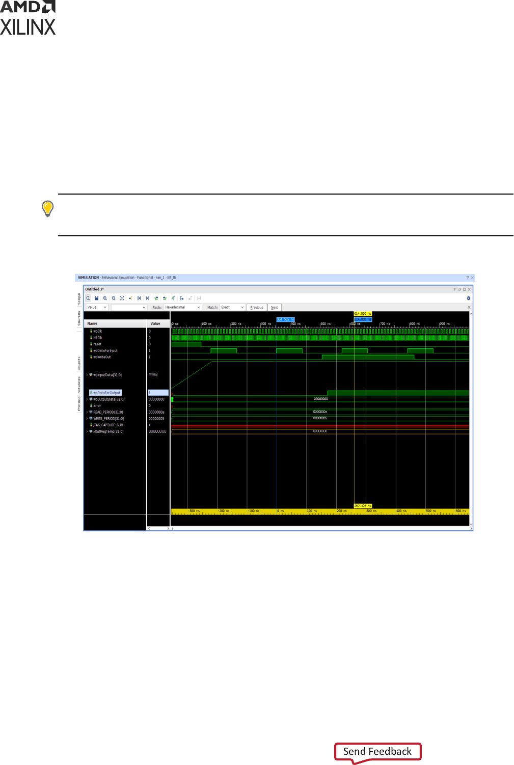
Related Information
Using Force Commands
Wave Window
When you invoke the simulator it opens a wave window by default. The wave window displays a
new wave conguraon consisng of the traceable HDL objects from the top module of the
simulaon, as shown in Wave Window.
TIP: On closing and reopening a project, you must rerun simulaon to view the wave window. If, however,
you unintenonally close the default wave window while a simulaon is acve, you can restore it by
selecng Window → Waveform from the main menu.
Figure 16: Wave Window
To add an individual HDL object or set of objects to the wave window: in the Objects window,
right-click an object or objects and select the Add to Wave Window opon from the context
menu (shown in Objects Window).
To add an object using the Tcl command type: add_wave <HDL_objects>.
Using the add_wave command, you can specify full or relave paths to HDL objects.
For example, if the current scope is /bft_tb/uut, the full path to the reset register under uut
is /bft_tb/uut/reset: the relave path is reset.
Chapter 4: Simulating with Vivado Simulator
UG900 (v2022.1) April 21, 2022 www.xilinx.com
Vivado Design Suite User Guide: Logic Simulation 60
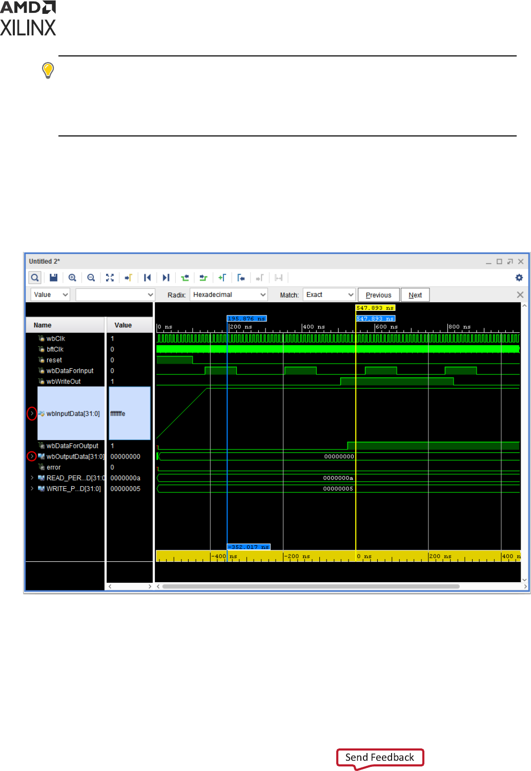
TIP: The
add_wave
command accepts HDL scopes as well as HDL objects. Using
add_wave
with a
scope is equivalent to the Add To Wave Window command in the Scope window. HDL objects of large bit
width can slow down the display of the waveform viewer. You can lter out such objects by seng a
display limit on the wave conguraon before issuing the Add to Wave Window command. To set a display
limit, use the Tcl command
set_property DISPLAY_LIMIT <maximum bit width>
[current_wave_config]
.
Wave Objects
The Vivado IDE Wave window is common across a number of Vivado Design Suite tools. An
example of the wave objects in a waveform conguraon is shown in the following gure.
Figure 17: HDL Objects in Waveform
The Wave window displays HDL objects, their values, and their waveforms, together with items
for organizing the HDL objects, such as: groups, dividers, and virtual buses.
Collecvely, the HDL objects and organizaonal items are called a wave conguraon. The
waveform poron of the Wave window displays addional items for me measurement, that
include: cursors, markers, and mescale rulers.
Chapter 4: Simulating with Vivado Simulator
UG900 (v2022.1) April 21, 2022 www.xilinx.com
Vivado Design Suite User Guide: Logic Simulation 61

The Vivado IDE traces the value changes of the HDL object in the Wave window during
simulaon, and you use the wave conguraon to examine the simulaon results.
The design hierarchy and the simulaon waveforms are not part of the wave conguraon, and
are stored in a separate wave database (WDB) le.
Context Menu in Waveform Window
When you right-click an object in the Waveform window, a context menu (shown in the following
gure) appears. See Understanding HDL Objects in Waveform Conguraons for more
informaon on HDL objects in Waveforms. The opons in the context menu are described below
• Go To Source Code: Opens the source code at the denion of the selected design wave
object.
• Show in Object Window: Displays the HDL objects for a design wave object in the Objects
window.
• Report Drivers: Display in the Tcl Console a report of the HDL processes that assign values to
the selected wave object.
• Force Constant: Forces the selected object to a constant value.
• Force Clock: Forces the selected object to an oscillang value.
• Remove Force: Removes any force on the selected object.
• Find: Opens the Find Toolbar in the Waveform window to search for a wave object by name.
• Find Value: Opens the Find Toolbar in the Waveform window to search a waveform for a
value.
• Select All: Selects all the wave objects in the Waveform window.
• Expand: Shows the sub-objects of the selected wave object.
• Collapse: Hides the sub-objects of the selected wave object.
• Ungroup: Unpacks the selected group or virtual bus.
• Rename: Changes the displayed name of the selected wave object.
• Name: Changes the display of the name of the selected wave object to show the full
hierarchical name (long name), the simple signal or bus name (short name), or a custom name.
• Waveform Style: Changes the waveform of the selected design wave object to digital or
analog format.
• Signal Color: Sets the waveform color of the selected design wave object.
• Divider Color: Sets the bar color of the selected divider.
• Radix: Sets the radix in which to display values of the selected design wave objects.
• Show as Enumeraon: Shows values of the selected SystemVerilog enumeraon wave object
as enumerator labels in place of numbers, whenever possible.
Chapter 4: Simulating with Vivado Simulator
UG900 (v2022.1) April 21, 2022 www.xilinx.com
Vivado Design Suite User Guide: Logic Simulation 62

• Reverse Bit Order: Reverses the bit order of values displayed for the selected array wave
object.
• New Group: Packs the selected wave objects into a folder-like group wave object.
• New Divider: Creates a horizontal separator in the list of the Waveform window's wave
objects.
• New Virtual Bus: Creates a new logic vector wave object consisng of the bits of the selected
design wave objects.
• Cut: Allows you to cut a signal in the Waveform window.
• Copy: Allows you to copy a signal in the Waveform window.
• Paste: Allows you to paste a signal in the Waveform window.
• Delete: Allows you to delete a signal in the Waveform window.
Chapter 4: Simulating with Vivado Simulator
UG900 (v2022.1) April 21, 2022 www.xilinx.com
Vivado Design Suite User Guide: Logic Simulation 63
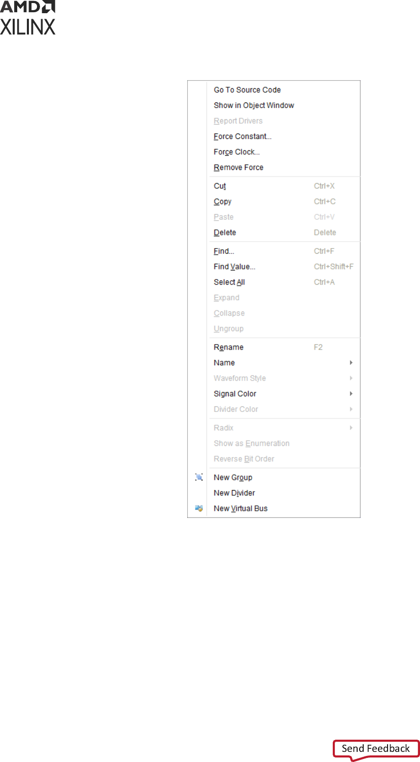
Figure 18: Context Menu of Waveform Objects Window
See Chapter 5: Analyzing Simulaon Waveforms with Vivado Simulator for more informaon
about using the Wave window.
Saving a Waveform Configuration
The new wave conguraon is not saved to disk automacally. Select File → Simulaon
Waveform → Save Conguraon As and supply a le name to save a WCFG le.
To save a wave conguraon to a WCFG le, type the Tcl command save_wave_config
<filename.wcfg>.
The specied command argument names and saves the WCFG le.
Chapter 4: Simulating with Vivado Simulator
UG900 (v2022.1) April 21, 2022 www.xilinx.com
Vivado Design Suite User Guide: Logic Simulation 64

IMPORTANT! Zoom sengs are not saved with the wave conguraon.
Related Information
Using Analog Waveforms
Changing the Format of SystemVerilog Enumeraons
Organizing Waveforms
Waveform Object Naming Styles
Using Force Commands
Searching a Value in Waveform Conguraon
Grouping Signals and Objects
Reversing the Bus Bit Order
Creating and Using Multiple Waveform
Configurations
In a simulaon session you can create and use mulple wave conguraons, each in its own
Wave window. When you have more than one Wave window displayed, the most recently-
created or recently-used window is the acve window. The acve window, in addion to being
the window currently visible, is the Wave window upon which commands external to the window
apply. For example: HDL Objects → Add to Wave Window.
You can set a dierent Wave window to be the acve window by clicking the tle of the window.
Related Information
Disnguishing Between Mulple Simulaon Runs
Creang a New Wave Conguraon
Running Functional and Timing Simulation
As soon as your project is created in the Vivado Design Suite, you can run behavioral simulaon.
You can run funconal and ming simulaons on your design aer successfully running synthesis
and/or implementaon. To run simulaon: in the Flow Navigator, select Run Simulaon and
choose the appropriate opon from the popup menu shown in the gure below.
TIP:
Availability of popup menu opons is dependent on the design development stage. For example, if you
have run synthesis but have not yet run implementaon, the implementaon opons in the popup menu
are grayed out.
Chapter 4: Simulating with Vivado Simulator
UG900 (v2022.1) April 21, 2022 www.xilinx.com
Vivado Design Suite User Guide: Logic Simulation 65
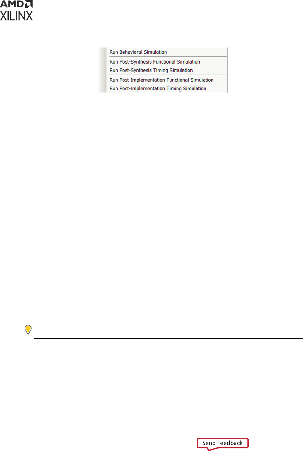
Figure 19: Simulation Run Options
Running Functional Simulation
Post-Synthesis Functional Simulation
You can view Run Simulaon → Post-Synthesis Funconal Simulaon opon (shown in the
previous gure) aer compleng a successful synthesis run.
Aer synthesis, the general logic design has been synthesized into device-specic primives.
Performing a post-synthesis funconal simulaon ensures that any synthesis opmizaons have
not aected the funconality of the design. Aer you select a post-synthesis funconal
simulaon, the funconal netlist is generated, and the UNISIM libraries are used for simulaon.
Post-Implementation Functional Simulations
The Run Simulaon → Post-Implementaon Funconal Simulaon opon (shown in the previous
gure) becomes available aer compleng implementaon run.
Aer implementaon, the design has been placed and routed in hardware. A funconal
vericaon at this stage is useful in determining if any physical opmizaons during
implementaon have aected the funconality of your design.
Aer you select a post-implementaon funconal simulaon, the funconal netlist is generated
and the UNISIM libraries are used for simulaon.
Running Timing Simulation
TIP:
Post-Synthesis ming simulaon uses the esmated ming delay from the device models and does not
include interconnect delay. Post-Implementaon ming simulaon uses actual ming delays.
When you run Post-Synthesis and Post-Implementaon ming simulaon the simulator tools
include:
• Gate-level netlist containing SIMPRIMS library components
• SECUREIP
• Standard Delay Format (SDF) les
Chapter 4: Simulating with Vivado Simulator
UG900 (v2022.1) April 21, 2022 www.xilinx.com
Vivado Design Suite User Guide: Logic Simulation 66

You dened the overall funconality of the design in the beginning. When the design is
implemented, accurate ming informaon is available.
To create the netlist and SDF, the Vivado Design Suite:
• Calls the netlist writer, write_verilog with the -mode timesim switch and write_sdf
(SDF annotator)
• Sends the generated netlist to the target simulator
You control these opons using Simulaon Sengs as described in Using Simulaon Sengs.
IMPORTANT! Post-Synthesis and Post-Implementaon ming simulaons are supported for Verilog only.
There is no support for VHDL ming simulaon. If you are a VHDL user, you can run post synthesis and
post implementaon funconal simulaon (in which case no SDF annotaon is required and the simulaon
netlist uses the UNISIM library). You can create the netlist using the write_vhdl Tcl command. For usage
informaon, refer to the Vivado Design Suite Tcl Command Reference Guide (UG835).
IMPORTANT! The Vivado simulator models use interconnect delays; consequently, addional switches
are required for proper ming simulaon, as follows:
-transport_int_delays -pulse_r 0 -
pulse_int_r 0
Post-Synthesis Timing Simulation
The Run Simulaon → Post-Synthesis Timing Simulaon opon (shown in the previous gure)
becomes available aer compleng a successful synthesis run.
Aer synthesis, the general logic design has been synthesized into device-specic primives, and
the esmated roung and component delays are available. Performing a post-synthesis ming
simulaon allows you to see potenal ming-crical paths prior to invesng in implementaon.
Aer you select a post-synthesis ming simulaon, the ming netlist and the esmated delays in
the SDF le are generated. The netlist les includes $sdf_annotate command so that the
simulaon tool includes the generated SDF le.
Post-Implementation Timing Simulations
The Run Simulaon → Post-Implementaon Timing Simulaon opon (shown in the previous
gure) becomes available aer compleng implementaon run.
Aer implementaon, the design has been implemented and routed in hardware. A ming
simulaon at this stage helps determine whether or not the design funconally operates at the
specied speed using accurate ming delays. This simulaon is useful for detecng
unconstrained paths, or asynchronous path ming errors, for example, on resets. Aer you select
a post-implementaon ming simulaon, the ming netlist and the SDF le are generated. The
netlist les includes $sdf_annotate command so that the generated SDF le is picked up.
When you specied simulaon sengs, you specied whether or not to create an SDF le and
whether the process corner would be set to fast or slow.
Chapter 4: Simulating with Vivado Simulator
UG900 (v2022.1) April 21, 2022 www.xilinx.com
Vivado Design Suite User Guide: Logic Simulation 67

TIP: To nd the SDF le oponal sengs, in the Vivado IDE Flow Navigator, right click Simulaon and
select Simulaon Sengs. In the Sengs dialog box, select Simulaon category and click Netlist tab.
Based on the specied process corner, the SDF le contains dierent min and max numbers.
Run two separate simulaons to check for setup and hold violaons.
To run a setup check, create an SDF le with -process_corner slow, and use the max column from
the SDF le.
To run a hold check, create an SDF le with the -process_corner fast, and use the min column
from the SDF le. The method for specifying which SDF delay eld to use is dependent on the
simulaon tool you are using. Refer to the specic simulaon tool documentaon for informaon
on how to set this opon.
To get full coverage run all four ming simulaons, specify as follows:
• Slow corner: SDFMIN and SDFMAX
• Fast corner: SDFMIN and SDFMAX
Saving Simulation Results
The Vivado simulator saves the simulaon results of the objects (VHDL signals, or Verilog reg or
wire) being traced to the Waveform Database (WDB) le (<filename>.wdb) in the
<project>.sim/<simset> directory.
If you add objects to the Wave window and run the simulaon, the design hierarchy for the
complete design and the transions for the added objects are automacally saved to the WDB
le. You can also add objects to the waveform database that are not displayed in the Wave
window using the log_wave command. For informaon about the log_wave command, see
Using the log_wave Tcl Command.
Distinguishing Between Multiple Simulation
Runs
When you have run several simulaons against a design, the Vivado simulator displays named
tabs at the top of the workspace with the simulaon type that is currently in the window
highlighted, as shown in the following gure.
Chapter 4: Simulating with Vivado Simulator
UG900 (v2022.1) April 21, 2022 www.xilinx.com
Vivado Design Suite User Guide: Logic Simulation 68
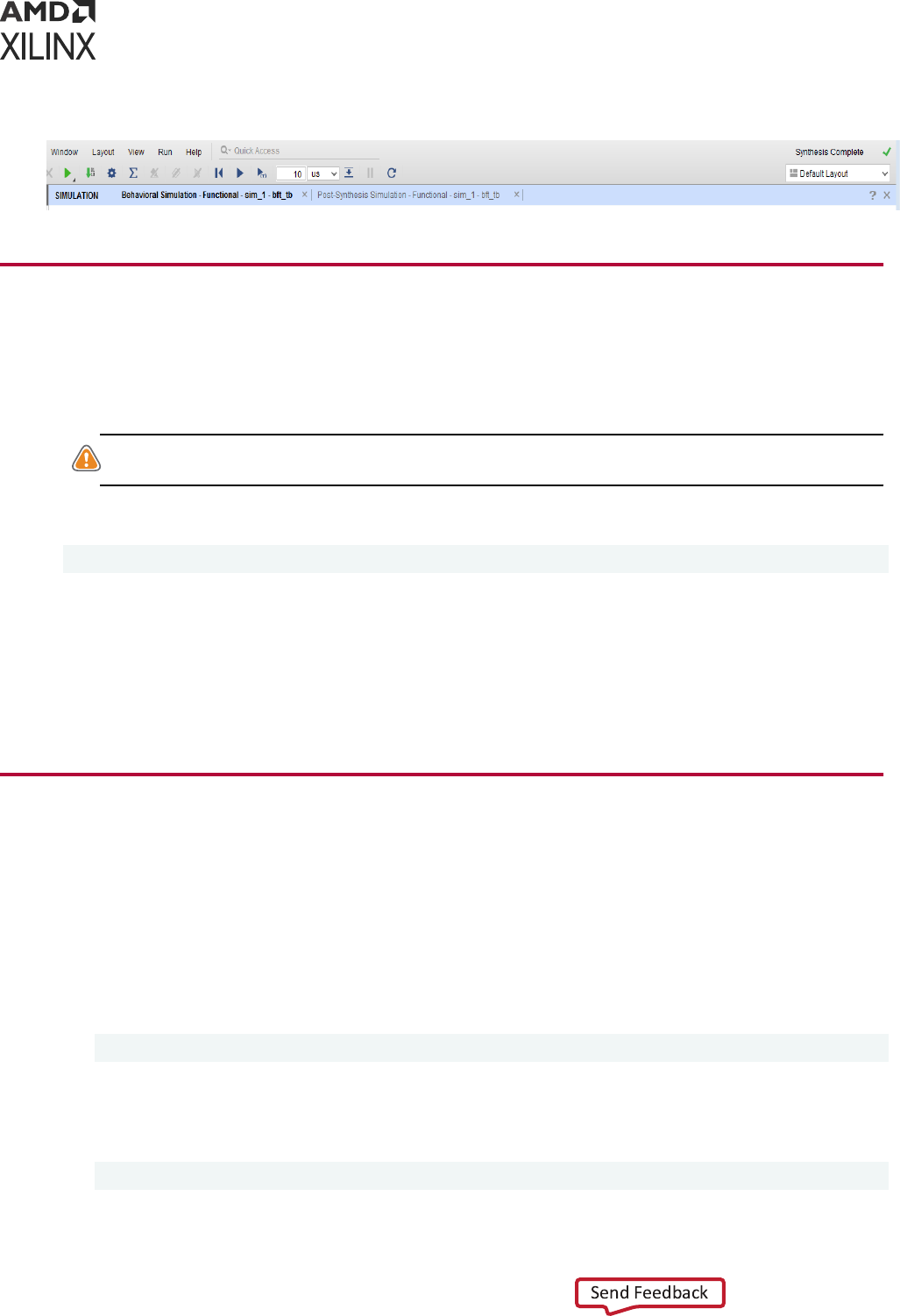
Figure 20: Active Simulation Type
Closing a Simulation
To close a simulaon, in the Vivado IDE:
Select File > Exit or click the X at the top-right corner of the project window.
CAUTION! When there are mulple simulaons running, clicking the X on the blue tle bar closes all
simulaons. To close a single simulaon, click the X on the small gray or white tab under the blue tle bar.
To close a simulaon from the Tcl Console, type:
close_sim
The Tcl command rst checks for unsaved wave conguraons. If any exist, the command issues
an error. Close or save unsaved wave conguraons before issuing the close_sim command, or
add the -force opon to the Tcl command.
Note: It is always recommended to use close_sim command to completely close the simulaon before
using close_project command to close the current project.
Adding a Simulation Start-up Script File
You can add custom Tcl commands in a batch le to the project so that they are run with the
simulaon. These commands are run aer simulaon begins. An example of this process is
described in the steps below.
1. Create a Tcl script with the simulaon commands you want to add to the simulaon source
les. For example, if you have a simulaon that runs for 1,000 ns, and you want it to run
longer, create a le that includes:
run 5us
Or, if you want to monitor signals that are not at the top level (because, by default, only top-
level signals are added to the waveform), you can add them to the post.tcl script. For
example:
add_wave/top/I1/<signalName>
Chapter 4: Simulating with Vivado Simulator
UG900 (v2022.1) April 21, 2022 www.xilinx.com
Vivado Design Suite User Guide: Logic Simulation 69
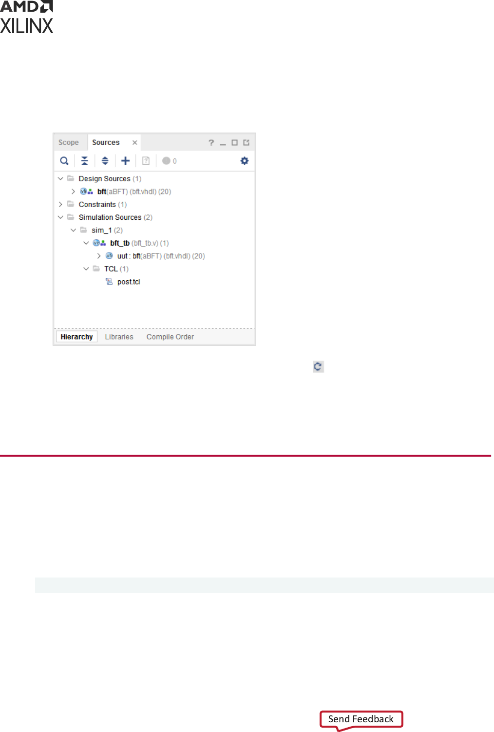
2. Name the le post.tcl and save it.
3. Use the Add Sources opon in Flow Navigator to invoke the Add Sources wizard, and select
Add or Create Simulaon Sources.
4. Add the post.tcl le to your Vivado Design Suite project as a simulaon source. The
post.tcl le displays in the Simulaon Sources folder, as shown in the following gure.
5. From the Simulaon toolbar, click the Relaunch buon .
Simulaon runs again, with the addional me you specied in the post.tcl le added to
the originally specied me. Noce that the Vivado simulator automacally sources the
post.tcl le aer invoking all its commands.
Viewing Simulation Messages
The Vivado IDE contains a message area where you can view informaonal, warning, and error
messages. As shown in the following gure, some messages from the Vivado simulator contain an
issue descripon and a suggested resoluon.
To see the same detail in the Tcl Console, type:
help -message {message_number}
Chapter 4: Simulating with Vivado Simulator
UG900 (v2022.1) April 21, 2022 www.xilinx.com
Vivado Design Suite User Guide: Logic Simulation 70
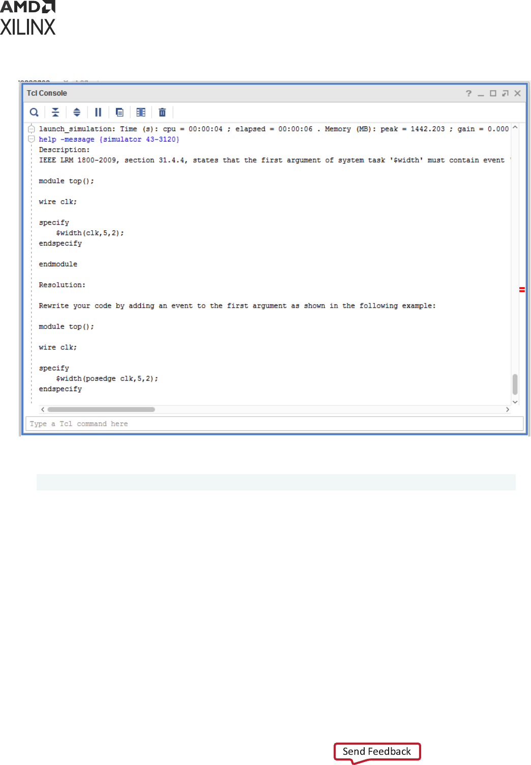
Figure 21: Simulator Message Description and Resolution Information
An example of such a command is as follows:
help -message {simulator 43-3120}
Managing Message Output
If your HDL design produces a large number of messages (for example, via the $display Verilog
system task or report VHDL statement), you can limit the amount of text output sent to the Tcl
Console and log le. This saves computer memory and disk space. To accomplish this, use the -
maxlogsize command line opon:
1. In the Flow Navigator, right-click on SIMULATION and select Simulaon Sengs.
2. In the Sengs dialog box, add -maxlogsize <size> next to
xsim.simulate.xsim.more_options, where <size> is the maximum amount of text
output in megabytes.
Chapter 4: Simulating with Vivado Simulator
UG900 (v2022.1) April 21, 2022 www.xilinx.com
Vivado Design Suite User Guide: Logic Simulation 71

Using the launch_simulation Command
The launch_simulation command lets you run any supported simulator in script mode.
The syntax of launch_simulation is as follows:
launch_simulation [-step <arg>] [-simset <arg>] [-mode <arg>] [-type <arg>]
[-scripts_only] [-of_objects <args>] [-absolute_path]
[-install_path <arg>] [-noclean_dir] [-quiet] [-
verbose][-gcc_install_path <arg>][-exec]
The following table describes the opons of launch_simulation.
Table 11: launch_simulation Options
Option Description
[-step]
Launch a simulation step. Values: all, compile, elaborate, simulate. Default: all (launch all
steps).
[-simset]
Name of the simulation fileset.
[-mode]
Simulation mode. Values: behavioral, post-synthesis, post-implementation Default: behavioral.
[-type]
Netlist type. Values: functional, timing. This is only applicable when the mode is set to post-
synthesis or post-implementation.
[-scripts_only]
Only generate scripts.
[-of_objects]
Generate compile order file for this object (applicable with -scripts_only option only)
[-absolute_path]
Make all file paths absolute with respect to the reference directory.
[-install_path]
Custom installation directory path.
[-noclean_dir]
Do not remove simulation run directory files.
[-quiet]
Ignore command errors.
[-verbose]
Suspend message limits during command execution.
[-gcc_install_path]
Specify GNU compiler installation directory path for g++/gcc executable
[-exec] Execute existing script for the step specified with the -step switch.
Examples
• Running behavioral simulaon using Vivado simulator
create_project project_1 project_1 -part xc7vx485tffg1157-1
add_files -norecurse tmp.v
add_files -fileset sim_1 -norecurse testbench.v
import_files -force -norecurse
update_compile_order -fileset sources_1
update_compile_order -fileset sim_1
launch_simulation
Chapter 4: Simulating with Vivado Simulator
UG900 (v2022.1) April 21, 2022 www.xilinx.com
Vivado Design Suite User Guide: Logic Simulation 72
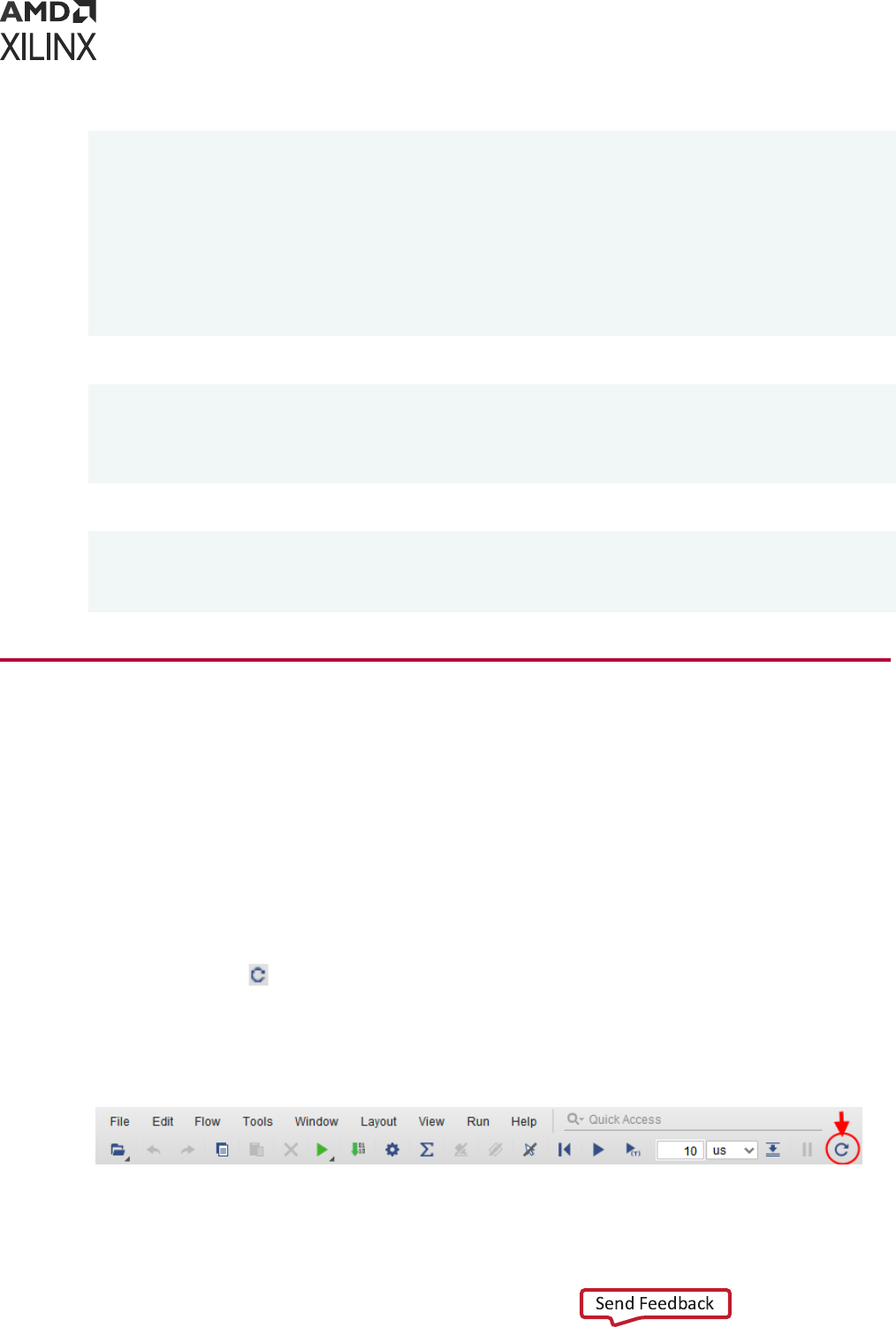
• Generang script for behavioral simulaon with Questa Advanced Simulator.
create_project project_1 project_1 -part xc7vx485tffg1157-1
add_files -norecurse tmp.v
add_files -fileset sim_1 -norecurse testbench.v
import_files -force -norecurse
update_compile_order -fileset sources_1
update_compile_order -fileset sim_1
set_property target_simulator Questa [current_project]
set_property compxlib.questa_compiled_library_dir
<compiled_library_location>
[current_project]
launch_simulation -scripts_only
• Launching post-synthesis funconal simulaon using Synopsys VCS
set_property target_simulator VCS [current_project]
set_property compxlib.vcs_compiled_library_dir
<compiled_library_location>
[current_project]
launch_simulation -mode post-synthesis -type functional
• Running post-implementaon ming simulaon using Synopsys VCS
set_property target_simulator vcs [current_project]
set_property compxlib.vcs_compiled_library_dir
<compiled_library_location> [current_project]
launch_simulation -mode post-implementation -type timing
Re-running the Simulation After Design
Changes (relaunch)
While debugging your HDL design with the Vivado simulator, you can determine that your HDL
source code needs correcon.
Use the following steps to modify your design and re-run the simulaon:
1. Use the Vivado code editor or other text editor to update and save any necessary source
code changes.
2. Use the Relaunch
buon on the Vivado IDE toolbar to re-compile and re-launch the
simulaon as shown in the following gure. You may alternavely use the relaunch_sim
Tcl command to re-compile and re-launch the simulaon.
Figure 22: Relaunch Sim Option
Chapter 4: Simulating with Vivado Simulator
UG900 (v2022.1) April 21, 2022 www.xilinx.com
Vivado Design Suite User Guide: Logic Simulation 73
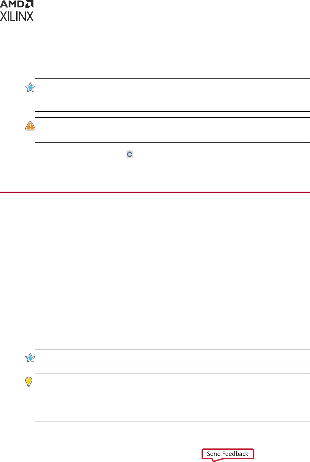
3. If the modied design fails to compile, an error box appears displaying the reason for failure.
The Vivado IDE connues to display the results of the previous run of the simulaon in a
disabled state. Return to step 1 to correct the errors and re-launch the simulaon again.
Aer the design successfully re-compiles, the simulaon starts again.
IMPORTANT! Relaunching may fail for reasons other than compilaon errors, such as in the case of a le
system error. If the Run buons on the Simulaon toolbar are grayed out aer a re-launch, indicang that
the simulaon is disabled, check the contents of the Tcl Console for possible errors that have prevented the
re-launch from succeeding.
CAUTION! You may also re-launch the simulaon using Run Simulaon in the Flow Navigator or using
launch_simulation
Tcl command. However, using these opons may fully close the simulaon,
discarding waveform changes and simulaon sengs such as radix customizaon.
Note: The Relaunch Simulaon buon will be acve only aer one successful run of Vivado simulator
using launch_simulation. The Relaunch Simulaon buon would be grayed out if the simulaon is run
in a Batch/Scripted mode.
Using the Saved Simulator User Interface
Settings
By default, the Vivado simulator saves your conguraon changes to a le under the simulaon's
working directory as you work with the user interface controls and Tcl commands of the Vivado
simulator. The sengs that are saved include the following:
• The state of the lter buons and column widths of the Scopes and Objects windows.
• Tcl properes of the simulaon, including array display limit, default radix, default me unit for
the run command, and trace limit.
• Radixes and the Show as Enumeraon state that you set on HDL objects in the Objects
window.
Aer you shut down the simulaon, the Vivado simulator restores your sengs when you
reopen and run the Vivado simulator.
IMPORTANT!
Turn o the Clean Up Simulaon Files check box in Vivado's Simulaon Sengs to ensure
that the sengs le does not get erased when you relaunch the simulaon.
TIP: To revert the sengs to their defaults, delete the sengs le. You can nd the sengs le under the
Vivado project directory at
<project>.sim/<simset>/<simtype>/xsim.dir/<snapshot>/
xsimSettings.ini
. For example, the sengs le for the default behavioral simulaon run of the BFT
example design would reside at
bft.sim/sim_1/behav/xsim.dir/bft_tb_behav/
xsimSettings.ini
. Alternavely, turn on the Clean Up Simulaon Files check box in the Simulaon
Sengs.
Chapter 4: Simulating with Vivado Simulator
UG900 (v2022.1) April 21, 2022 www.xilinx.com
Vivado Design Suite User Guide: Logic Simulation 74

Default Settings
A Vivado
®
project Tcl object supports a few properes that allows you to supply default sengs
for cleaned up or newly created simulaons. These simulaons do not already have a sengs
le. The following list shows the default sengs properes of the project:
• XSIM.ARRAY_DISPLAY_LIMIT
• XSIM.RADIX
• XSIM.TIME_UNIT
• XSIM.TRACE_LIMIT
You can view the current values of the properes with the report_property
[current_project] Tcl command and set the values of the properes with the
set_property <property name> <property value> [current_project] Tcl
command. For example, to set the array display limit to 16, use the following command.
set_property xsim.array_display_limit 16 [current_project]
When you launch the new or cleaned-up simulaon, the simulaon Tcl object inherits your
project properes. You can verify it with the following Tcl command:
report_property [current_sim]
IMPORTANT!
The project properes apply only to cleaned-up or newly created simulaons. Aer you
have run a simulaon of a parcular run type and sim set such as
sim_1/behav
, that simulaon retains
a separate copy of the sengs for all subsequent launches. The changes to the project properes can no
longer take eect for that simulaon. The project properes take eect again only if the simulaon is
cleaned up or the sengs le is deleted.
Chapter 4: Simulating with Vivado Simulator
UG900 (v2022.1) April 21, 2022 www.xilinx.com
Vivado Design Suite User Guide: Logic Simulation 75

Chapter 5
Analyzing Simulation Waveforms
with Vivado Simulator
In the Vivado
®
simulator, you can use the waveform to analyze your design and debug your code.
The simulator populates design signal data in other areas of the workspace, such as the Objects
and the Scope windows.
Typically, simulaon is set up in a test bench where you dene the HDL objects you want to
simulate. For more informaon about test benches see Wring Ecient Test Benches (XAPP199).
When you launch the Vivado simulator, a wave conguraon displays with top-level HDL
objects. The Vivado simulator populates design data in other areas of the workspace, such as the
Scope and Objects windows. You can then add addional HDL objects, or run the simulaon. See
Using Wave Conguraons and Windows below.
Using Wave Configurations and Windows
Vivado simulator allows customizaon of the wave display. The current state of the display is
called the wave conguraon. This conguraon can be saved for future use in a WCFG le.
A wave conguraon can have a name or be untitled. The name shows on the tle bar of the
wave conguraon window. A wave conguraon is untled when it has never been saved to a
le.
Creating a New Wave Configuration
Create a new waveform conguraon for displaying waveforms as follows:
1. Select File → Simulaon Waveform → New Conguraon.
A new Wave window opens and displays a new, untled waveform conguraon. Tcl
command: create_wave_config <waveform_name>.
2. Add HDL objects to the waveform conguraon using the steps listed in Understanding HDL
Objects in Waveform Conguraons .
Chapter 5: Analyzing Simulation Waveforms with Vivado Simulator
UG900 (v2022.1) April 21, 2022 www.xilinx.com
Vivado Design Suite User Guide: Logic Simulation 76

See Chapter 4: Simulang with Vivado Simulator for more informaon about creang new
waveform conguraons. Also see Creang and Using Mulple Waveform Conguraons for
informaon on mulple waveforms.
Opening a WCFG File
Open a WCFG le to use with the simulaon as follows:
1. Select File > Simulaon Waveform > Open Conguraon .
The Open Waveform Conguraon dialog box opens.
2. Locate and select a WCFG le.
Note: When you open a WCFG le that contains references to HDL objects that are not present in a
stac simulaon HDL design hierarchy, the Vivado simulator ignores those HDL objects and omits
them from the loaded waveform conguraon.
A Wave window opens, displaying waveform data that the simulator nds for the listed wave
objects of the WCFG le.
Tcl command: open_wave_config <waveform_name>
Saving a Wave Configuration
Aer eding, to save a wave conguraon to a WCFG le, select File → Simulaon Waveform →
Save Conguraon As, and type a name for the waveform conguraon.
Tcl command: save_wave_config <waveform_name>
Opening a Previously Saved Simulation Run
There are three methods for opening a previously saved simulaon using the Vivado Design
Suite: an interacve method and a programmac method.
Standalone mode
You can open WDB le outside Vivado using the following command:
xsim <name>.wdb -gui
TIP:
You can open a WCFG le together with the WDB le by adding
-view <WCFG file>
to the
xsim
command.
Interacve Method
Chapter 5: Analyzing Simulation Waveforms with Vivado Simulator
UG900 (v2022.1) April 21, 2022 www.xilinx.com
Vivado Design Suite User Guide: Logic Simulation 77

• If a Vivado Design Suite project is loaded, click Flow → Open Stac Simulaon and select the
WDB le containing the waveform from the previously run simulaon.
TIP: A stac simulaon is a mode of the Vivado simulator in which the simulator displays data from a
WDB le in its windows in place of data from a running simulaon.
• Alternavely, in the Tcl Console, run: open_wave_database <name>.wdb.
Programmac Method
Create a Tcl le (for example, design.tcl) with contents:
current_fileset
open_wave_database <name>.wdb
Then run it as:
vivado -source design.tcl
IMPORTANT! Vivado simulator can open WDB les created on any supported operang system. It can
also open WDB les created in Vivado Design Suite versions 2014.3 and later. Vivado simulator cannot
open WDB les created in versions earlier than 2014.3 of the Vivado Design Suite.
When you run a
simulaon and display HDL objects in a Wave window, the running simulaon
produces a waveform database (WDB) le containing the waveform acvity of the displayed
HDL objects. The WDB le also stores informaon about all the HDL scopes and objects in the
simulated design. In this mode you cannot use commands that control or monitor a simulaon,
such as run commands, as there is no underlying 'live' simulaon model to control.
However, you can view waveforms and the HDL design hierarchy in a stac simulaon.
Understanding HDL Objects in Waveform
Configurations
When you add an HDL object to a waveform conguraon, the waveform viewer creates a wave
object of the HDL object. The wave object is linked to, but disnct from, the associated HDL
object.
You can create mulple wave objects from the same HDL object, and set the display properes
of each wave object separately.
For example, you can set one wave object for an HDL object named myBus to display values in
hexadecimal and another wave object for myBus to display values in decimal.
Chapter 5: Analyzing Simulation Waveforms with Vivado Simulator
UG900 (v2022.1) April 21, 2022 www.xilinx.com
Vivado Design Suite User Guide: Logic Simulation 78
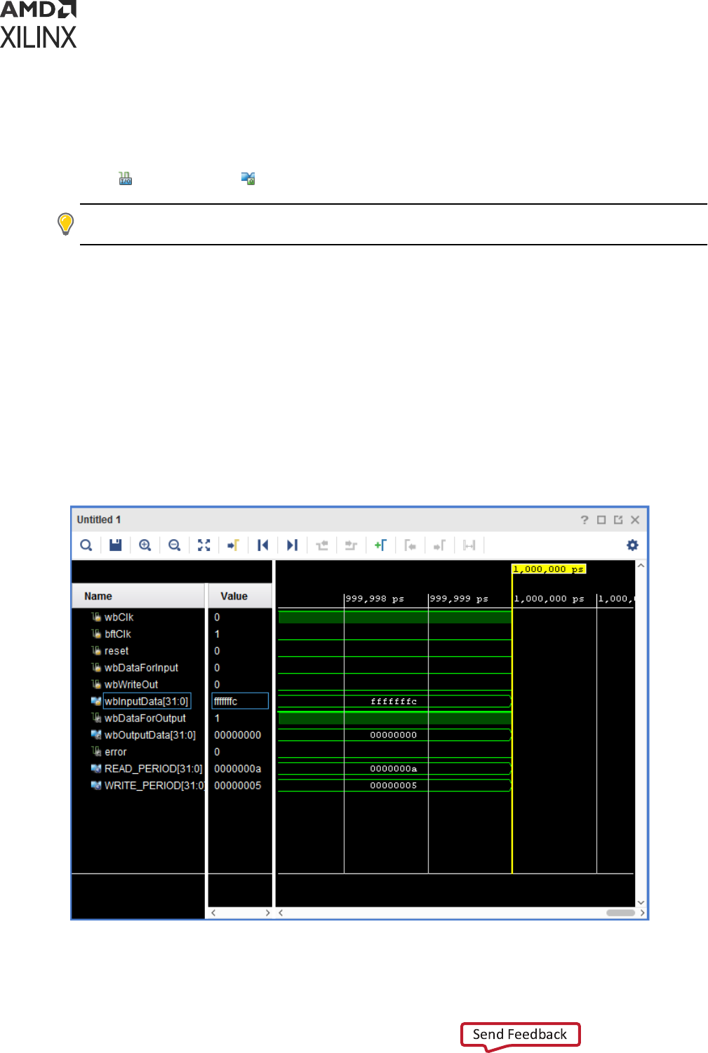
There are other kinds of wave objects available for display in a waveform conguraon, such as:
dividers, groups, and virtual buses.
Wave objects created from HDL objects are specically called design wave objects. These objects
display with a corresponding icon. For design wave objects, the icon indicates whether the object
is a scalar
or a compound such as a Verilog vector or VHDL record.
TIP: To view the HDL object for a design wave object in the Objects window, right-click the name of the
design wave object and choose Show in Object Window.
The following gure shows an example of HDL objects in the waveform conguraon window.
The design objects display Name and Value.
• Name: By default, shows the short name of the HDL object: the name alone, without the
hierarchical path of the object. You can change the Name to display a long name with full
hierarchical path or assign it a custom name.
• Value: Displays the value of the object at the me indicated in the main cursor of the wave
window. You can change the formang, or radix, of the value independent of the formang
of other design wave objects linked to the same HDL object and independent of the
formang of values displayed in the Objects window and source code window.
Figure 23: Waveform HDL Objects
Chapter 5: Analyzing Simulation Waveforms with Vivado Simulator
UG900 (v2022.1) April 21, 2022 www.xilinx.com
Vivado Design Suite User Guide: Logic Simulation 79

The Scope window provides the ability to add all viewable HDL objects for a selected scope to
the wave window. For informaon on using the Scope window, see Scope Window.
About Radixes
Understanding the type of data on your bus is important, and to use the digital and analog
waveform opons eecvely, you need to recognize the relaonship between the radix seng
and the data type.
IMPORTANT! Make a change to the radix seng in the window in which you wish to see the change. A
change to the radix of an item in the Objects window does not apply to values in the Wave window or the
Tcl Console. For example, the item wbOutputData[31:0] can be set to Signed Decimal in the objects
window, but it remains set to Binary in the Wave window.
Changing the Default Radix
The default waveform radix controls the numerical format of values for all wave objects whose
radix you did not explicitly set. The waveform radix defaults to Hexadecimal.
To change the default waveform radix:
1. In the Waveform window, click the Sengs buon
to open the Waveform Sengs.
2. On the General page, click the Default Radix drop-down menu.
3. From the drop-down list, select a radix.
Changing the Radix on Individual Objects
To change the radix of a wave object in the Wave window:
1. Right-click the wave object name.
2. Select Radix and the format you want from the drop-down menu:
• Default
• Binary
• Hexadecimal
• Octal
• ASCII
• Unsigned Decimal
• Signed Decimal
• Signed Magnitude
• Real
Chapter 5: Analyzing Simulation Waveforms with Vivado Simulator
UG900 (v2022.1) April 21, 2022 www.xilinx.com
Vivado Design Suite User Guide: Logic Simulation 80
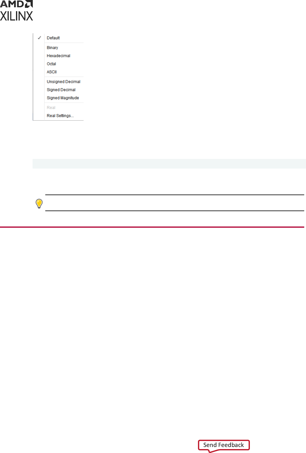
Note: For a descripon of the usage for Real and Real Sengs see Using Analog Waveforms
3. From the Tcl Console, to change the numerical format of the displayed values, type the
following Tcl command:
set_property radix <radix> <hdl_object>
Where <radix> is one the following: bin, unsigned, hex, dec, ascii, or oct and where
<wave_object> is an object returned by the add_wave command.
TIP: If you change the radix in the Wave window, it will not be reected in the Objects window.
Customizing the Waveform
Using Analog Waveforms
Using Radixes and Analog Waveforms
Bus values are interpreted as numeric values, which are determined by the radix seng on the
bus wave object, as follows:
• Binary, octal, hexadecimal, ASCII, and unsigned decimal radixes cause the bus values to be
interpreted as unsigned integers.
• If any bit in the bus is neither 0 nor 1, the enre bus value is interpreted as 0.
• The signed decimal and signed magnitude radixes cause the bus values to be interpreted as
signed integers.
• Real radixes cause bus values to be interpreted as xed point or oang point real numbers,
based on sengs of the Real Sengs dialog box.
To set a wave object to the Real radix:
Chapter 5: Analyzing Simulation Waveforms with Vivado Simulator
UG900 (v2022.1) April 21, 2022 www.xilinx.com
Vivado Design Suite User Guide: Logic Simulation 81
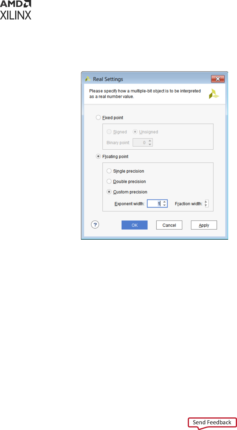
1. In the waveform conguraon window, select an HDL object, and right-click to open the
popup menu.
2. Select Radix → Real Sengs to open the Real Sengs dialog box, shown in the following
gure.
You can set the radix of a wave to Real to display the values of the object as real numbers. Before
selecng this radix, you must choose sengs to instruct the waveform viewer how to interpret
the bits of the values.
The Real Seng dialog box opons are:
• Fixed Point: Species that the bits of the selected bus wave object(s) is interpreted as a xed
point, signed, or unsigned real number.
• Binary Point: Species how many bits to interpret as being to the right of the binary point. If
Binary Point is larger than the bit width of the wave object, wave object values cannot be
interpreted as xed point, and when the wave object is shown in Digital waveform style, all
values show as <Bad Radix>. When shown as analog, all values are interpreted as 0.
• Floang Point: Species that the bits of the selected bus wave object(s) should be interpreted
as an IEEE oang point real number.
Note: Only single precision and double precision (and custom precision with values set to those of single
and double precision) are supported.
Chapter 5: Analyzing Simulation Waveforms with Vivado Simulator
UG900 (v2022.1) April 21, 2022 www.xilinx.com
Vivado Design Suite User Guide: Logic Simulation 82

Other values result in <Bad Radix> values as in Fixed Point. Exponent Width and Fracon
Width must add up to the bit width of the wave object, or else <Bad Radix> values result.
TIP: If the row indices separator lines are not visible, you can turn them on in the Using the Waveform
Sengs Dialog Box, to make them visible.
Displaying Waveforms as Analog
IMPORTANT! When viewing an HDL bus object as an analog waveform—to produce the expected
waveform, select a radix that matches the nature of the data in the HDL object. For example:
• If the data encoded on the bus is a 2's-compliment signed integer, you must choose a signed
radix.
• If the data is oang point encoded in IEEE format, you must choose a real radix.
Customizing the Appearance of Analog Waveforms
To customize the appearance of an analog waveform, right-click an HDL object in the Name
column of the waveform conguraon window and select Waveform Style from the drop-down
menu. A popup menu appears, showing the following opons:
• Analog: Sets the waveform to Analog.
• Digital: Sets the waveform object to Digital.
• Analog Sengs: Opens the Analog Sengs dialog box (shown in the following gure), which
provides opons for the analog waveform display.
The Wave window can display analog waveforms only for buses that are 64 bits wide or smaller.
Chapter 5: Analyzing Simulation Waveforms with Vivado Simulator
UG900 (v2022.1) April 21, 2022 www.xilinx.com
Vivado Design Suite User Guide: Logic Simulation 83
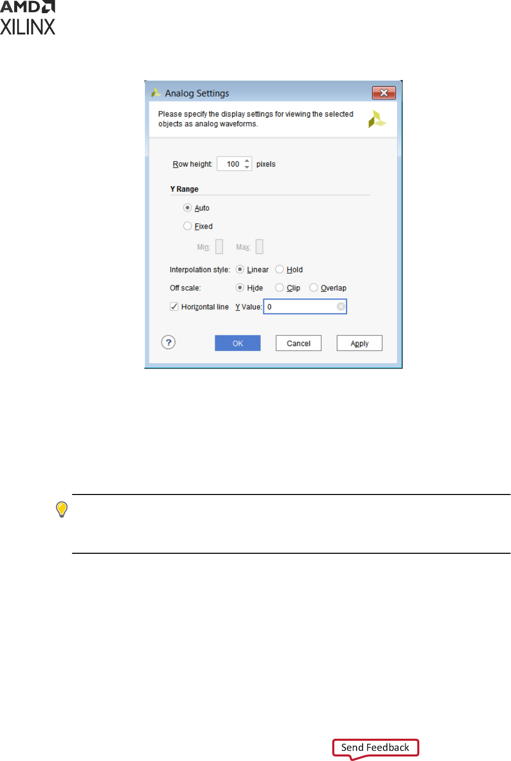
Figure 24: Analog Settings Dialog Box
Analog Settings Dialog Box Option Descriptions
• Row Height: Species how tall to make the select wave object(s), in pixels. Changing the row
height does not change how much of a waveform is exposed or hidden vercally, but rather
stretches or contracts the height of the waveform.
When switching between Analog and Digital waveform styles, the row height is set to an
appropriate default for the style (20 for digital, 100 for analog).
TIP: If the row indices separator lines are not visible, enable the checkbox in the Waveform Sengs to
turn them on. Using the Waveform Sengs Dialog Box for informaon on how to change the opons
sengs. You can also change the row height by dragging the row index separator line to the le and
below the waveform name.
• Y Range: Species the range of numeric values to be shown in the waveform area.
○ Auto: Species that the range should connually expand whenever values in the visible
me range of the window are discovered to lie outside the current range.
○ Fixed: Species that the me range is to remain at a constant interval.
○ Min: Species the value displays at the boom of the waveform area.
○ Max: Species the value displays at the top.
Chapter 5: Analyzing Simulation Waveforms with Vivado Simulator
UG900 (v2022.1) April 21, 2022 www.xilinx.com
Vivado Design Suite User Guide: Logic Simulation 84

Both values can be specied as oang point; however, if the wave object radix is integer, the
values are truncated to integers.
• Interpolaon Style: Species how the line connecng data points is to be drawn.
○ Linear: Species a straight line between two data points.
○ Hold: Species that of two data points, a horizontal line is drawn from the le point to the
X-coordinate of the right point, then another line is drawn connecng that line to the right
data point, in an L shape.
• O Scale: Species how to draw waveform values that lie outside the Y range of the
waveform area.
○ Hide: Species that outlying values are not shown, such that a waveform that reaches the
upper or lower bound of the waveform area disappears unl values are again within the
range.
○ Clip: Species that outlying values be altered so that they are at the top or boom of the
waveform area, so a waveform that reaches the upper- or lower-bound of the waveform
area follows the bound as a horizontal line unl values are once again within the range.
○
Overlap: Species that the waveform be drawn wherever its values are, even if they lie
outside the bounds of the waveform area and overlap other waveforms, up to the limits of
the Wave window itself.
• Horizontal Line: Species whether to draw a horizontal rule at the given value. If the check-
box is on, a horizontal grid line is drawn at the vercal posion of the specied Y value, if that
value is within the Y range of the waveform.
As with Min and Max, the Y value accepts a oang point number but truncates it to an
integer if the radix of the selected wave objects is an integer.
Waveform Object Naming Styles
There are opons for renaming objects, viewing object names, and changing name displays.
Renaming Objects
You can rename any wave object in the waveform conguraon, such as design wave objects,
dividers, groups, and virtual buses.
1. Select the object name in the Name column.
2. Right-click and select Rename from the popup menu.
The Rename dialog box opens.
3. Type the new name in the Rename dialog box, and click OK.
Note: Changing the name of a design wave object in the wave conguraon does not aect the name
of the underlying HDL object.
Chapter 5: Analyzing Simulation Waveforms with Vivado Simulator
UG900 (v2022.1) April 21, 2022 www.xilinx.com
Vivado Design Suite User Guide: Logic Simulation 85
Changing the Object Display Name
You can display the full hierarchical name (long name), the simple signal or bus name (short
name), or a custom name for each design wave object. The object name displays in the Name
column of the wave conguraon. If the name is hidden:
1. Expand the Name column unl you see the enre name.
2. In the Name column, use the scroll bar to view the name.
To change the display name:
1. Select one or more signal or bus names. Use Shi+click or Ctrl+click to select many signal
names.
2. Right-click and select Name from the drop-down menu. A popup menu appears, showing the
following opons:
• Long to display the full hierarchical name of the design object.
• Short to display the name of the signal or bus only.
• Custom to display the custom name given to the object when renamed. See Changing the
Object Display Name.
TIP: Renaming a wave object changes the name display mode to Custom. To restore the original name
display mode, change the display mode to Long or Short, as described above. Long and Short names
are meaningful only to design wave objects. Other wave objects (dividers, groups, and virtual buses)
display their Custom names by default and display an ID string for their Long and Short names.
Reversing the Bus Bit Order
You can reverse the bus bit order in the wave conguraon to switch between MSB-rst (big
endian) and LSB-rst (lile endian) bit order for the display of bus values.
To reverse the bit order:
1. Select a bus.
2. Right-click and select Reverse Bit Order.
The bus bit order reverses. The Reverse Bit Order command is marked to show that this is the
current behavior.
IMPORTANT!
The Reverse Bit Order command operates only on the values displayed on the bus. The
command does not reverse the list of bus elements that appears below the bus when you expand the
bus wave object.
TIP: The index ranges displayed on Long and Short names of buses indicate the bit order in bus
elements. For example, aer applying Reverse Bit Order on a bus
bus[0:7]
, the bus displays
bus[7:0]
.
Chapter 5: Analyzing Simulation Waveforms with Vivado Simulator
UG900 (v2022.1) April 21, 2022 www.xilinx.com
Vivado Design Suite User Guide: Logic Simulation 86

Changing the Format of SystemVerilog
Enumerations
A SystemVerilog enumeraon is an HDL object with numerical values for which text labels are
dened to represent specic values. For example, an enumeraon might dene LABEL1 to
represent the value 1 and LABEL2 to represent the value 5. The Show As Enumeraon opon on
the context menu lets you specify whether to show enumeraon values using their given labels
or numerically. In the previous example, if Show As Enumeraon is on, a value of 5 appears as
LABEL2. If the opon is o, the value 5 appears as in whatever radix is set for the enumeraon,
as shown in the Radix menu.
To display enumeraons using labels:
1. Select an enumeraon
2. Right-click and check Display As Enumeraon
To display enumeraons numerically:
1. Select an enumeraon
2. Right-click and uncheck Display As Enumeraon
Note: Enumeraon values for which there is no dened label always display numerically, regardless of
the Display As Enumeraon seng. The Display As Enumeraon opon is enabled only for
SystemVerilog enumeraon objects.
Controlling the Waveform Display
You can control the waveform display using:
• Resizing handles between the Name, Value, and waveform columns of the wave window
• Scroll combinaons with the mouse wheel
• Zoom feature buons in the Wave window sidebar
• Zoom combinaons with the mouse wheel
• Vivado IDE Y-Axis zoom gestures
• Vivado simulaon X-Axis zoom gestures. See the Vivado Design Suite User Guide: Using the
Vivado IDE (UG893) for more informaon about using the mouse to pan and zoom.
Note: In contrast to other Vivado Design Suite graphic windows, zooming in a Wave window applies to
the X (me) axis independent of the Y axis. As a result, the Zoom Range X gesture, which species a
range of me to which to zoom the window, replaces the Zoom to Area gesture of other Vivado Design
Suite windows.
Chapter 5: Analyzing Simulation Waveforms with Vivado Simulator
UG900 (v2022.1) April 21, 2022 www.xilinx.com
Vivado Design Suite User Guide: Logic Simulation 87

TIP: Saving a WCFG le records wave window sengs in addion to wave objects and markers. Wave
window sengs include the Name and Value column widths, zoom level, scroll posion, expansion state
of groups and buses, and the posion of the main cursor.
Using the Column Resizing Handles
To change the width of the Name or Value column, posion the mouse over the vercal bar to
the right of the column unl the mouse cursor changes shape, then drag the mouse le or right
to narrow or widen the column as desired.
Note: You may need to widen the Value column rst to widen the Name column, if the Value column's
width is already at its minimum.
Scrolling with the Mouse Wheel
Click within the wave window to scroll up and down with the mouse wheel. You can also scroll
the waveform le and right with the mouse wheel in combinaon with the Shi key.
Using the Zoom Feature Buttons
There are zoom funcons such as Zoom in, Zoom Out, and Zoom Fit as menu buons in the
Wave window that let you zoom in and out of a wave conguraon as needed.
Zooming with the Mouse Wheel
Click within the waveform area and use the mouse wheel in combinaon with the Ctrl key to
zoom in and out, emulang the operaon of the dials on an oscilloscope.
Y-Axis Zoom Gestures for Analog Waveforms
In addion to the zoom gestures supported for zooming in the X dimension, when over an analog
waveform, addional zoom gestures are available, as shown in the following gure.
Chapter 5: Analyzing Simulation Waveforms with Vivado Simulator
UG900 (v2022.1) April 21, 2022 www.xilinx.com
Vivado Design Suite User Guide: Logic Simulation 88
Figure 25: Analog Zoom Options
Zoom
Out
Y
Zoom Y
Range
Zoom
In
X
Zoom
X
Range
Zoom
Fit
X
Reset
Zoom
Y
Zoom
Out
X
Zoom
In
Y
To invoke a zoom gesture, hold down the le mouse buon and drag in the direcon indicated in
the diagram, where the starng mouse posion is the center of the diagram.
The addional zoom gestures are:
• Zoom Out Y: Zooms out in the Y dimension by a power of 2 determined by how far away the
mouse buon is released from the starng point. The zoom is performed such that the Y value
of the starng mouse posion remains staonary.
• Zoom Y Range: Draws a vercal curtain which species the Y range to display when the
mouse is released.
• Zoom In Y: Zooms in toward the Y dimension by a power of 2 determined by how far away
the mouse buon is released from the starng point. The zoom is performed such that the Y
value of the starng mouse posion remains staonary.
• Reset Zoom Y: Resets the Y range to that of the values currently displayed in the Wave
window and sets the Y Range mode to Auto.
All zoom gestures in the Y dimension set the Y Range analog sengs. Reset Zoom Y sets the Y
Range to Auto, whereas the other gestures set Y Range to Fixed.
Chapter 5: Analyzing Simulation Waveforms with Vivado Simulator
UG900 (v2022.1) April 21, 2022 www.xilinx.com
Vivado Design Suite User Guide: Logic Simulation 89
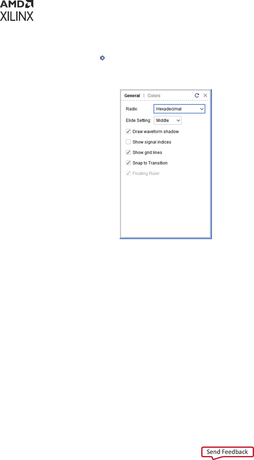
Using the Waveform Settings Dialog Box
Click the Sengs buon to open the Waveform Sengs as shown in the following gure.
Figure 26: Waveform Settings
From the General tab, you can congure the following Waveform Sengs:
• Radix: Sets the numerical format to use for newly-created design wave objects.
• Elide Seng: Controls truncaon of signal names that are too long for the Wave window.
○ Le truncates the le end of long names.
○ Right truncates the right end of long names.
○ Middle preserves both the le and right ends, oming the middle part of long names.
• Draw Waveform Shadow: Creates a shaded representaon of the waveform.
• Show signal indices: Displays the row numbers to the le of each wave object name. You can
drag the lines separang the row numbers to change the height of a wave object.
• Show grid lines: Displays the wave window with grid lines.
• Snap to Transion: When selected, causes dragged cursors and markers to gravitate to
waveform transions near the mouse cursor. See Using Cursors for more informaon.
• Floang Ruler: Displays the oang ruler whenever the secondary cursor is visible or a marker
is selected. See Using the Floang Ruler for more informaon.
Chapter 5: Analyzing Simulation Waveforms with Vivado Simulator
UG900 (v2022.1) April 21, 2022 www.xilinx.com
Vivado Design Suite User Guide: Logic Simulation 90

TIP: If Floang Ruler opon appears disabled (unchecked) in the Sengs dialog box, use Shi+Click on
the Wave window to make the secondary cursor visible. This acon results in enabling the Floang
Ruler opon in the Sengs dialog box.
• From the Colors tab, you can set colors of items within the waveform.
Changing the Display of the Time Scale
Right-click above the ruler to display the me scale menu. This menu lets you select how you
want to display me values on the me scale.
The following are the opons on the mescale menu:
• Auto: The mescale choses me units suitable for the wave window's zoom level.
• Default: Displays the me units corresponding to the precision of the simulaon that was
determined when the HDL design was compiled.
• Samples: Displays the me in discrete sample numbers instead of fracons of a second (not
available for HDL simulaon).
• User: User-dened me units (not available for HDL simulaon).
• fs: Displays me units in femtoseconds.
• ps: Displays me units in picoseconds.
• ns: Displays me units in nanoseconds.
• us: Displays me units in microseconds.
• ms: Displays me units in milliseconds.
• s: Displays me units in seconds
Organizing Waveforms
The following subsecons describe the opons that let you organize informaon within a
waveform.
Grouping Signals and Objects
A Group is an expandable and collapsible container for organizing related sets of wave objects.
The Group itself displays no waveform data but can be expanded to show its contents or
collapsed to hide them. You can add, change, and remove groups.
To add a Group:
1. In a Wave window, select one or more wave objects to add to a group.
Chapter 5: Analyzing Simulation Waveforms with Vivado Simulator
UG900 (v2022.1) April 21, 2022 www.xilinx.com
Vivado Design Suite User Guide: Logic Simulation 91
Note: A group can include dividers, virtual buses, and other groups.
2. Right-click and select New Group from the context menu.
This adds a Group that contains the selected wave object to the wave conguraon.
In the Tcl Console, type add_wave_group to add a new group.
A Group is represented with the Group buon . You can move other HDL objects to the group
by dragging and dropping the signal or bus name.
The new Group and its nested wave objects saves when you save the waveform conguraon
le.
You can move or remove Groups as follows:
• Move Groups to another locaon in the Name column by dragging and dropping the group
name.
• Remove a Group by highlighng it, right-click and select Ungroup from the popup menu.
Wave objects formerly in the Group are placed at the top-level hierarchy in the wave
conguraon.
Groups can be renamed also; see Changing the Object Display Name.
CAUTION!
The Delete key removes a selected group and its nested wave objects from the wave
conguraon.
Using Dividers
Dividers create a visual separator between HDL objects to make certain signals or objects easier
to see. You can add a divider to your wave conguraon to create a visual separator of HDL
objects, as follows:
1. In a Name column of the Wave window, click a signal to add a divider below that signal.
2. Right-click and select New Divider.
The new divider is saved with the wave conguraon le when you save the le.
Tcl command: add_wave_divider
You can move or delete Dividers as follows:
• To move a Divider to another locaon in the waveform, drag and drop the divider name.
• To delete a Divider, highlight the divider, and click the Delete key, or right-click and select
Delete from the context menu.
Dividers can be renamed also; see Changing the Object Display Name.
Chapter 5: Analyzing Simulation Waveforms with Vivado Simulator
UG900 (v2022.1) April 21, 2022 www.xilinx.com
Vivado Design Suite User Guide: Logic Simulation 92
Defining Virtual Buses
You dene a virtual bus to the wave conguraon, which is a grouping to which you can add
logic scalars and vectors.
The virtual bus displays a bus waveform, whose values are composed by taking the
corresponding values from the added scalars and arrays in the vercal order that they appear
under the virtual bus and aening the values to a one-dimensional vector.
To add a virtual bus:
1. In a wave conguraon, select one or more wave objects to add to a virtual bus.
2. Right-click and select New Virtual Bus from the popup menu.
The virtual bus is represented with the Virtual Bus buon
.
Tcl Command: add_wave_virtual_bus
You can move other logical scalars and arrays to the virtual bus by dragging and dropping the
signal or bus name.
The new virtual bus and its nested items save when you save the wave conguraon le. You can
also move it to another locaon in the waveform by dragging and dropping the virtual bus name.
You can rename a virtual bus; see Changing the Object Display Name.
To remove a virtual bus, and ungroup its contents, highlight the virtual bus, right-click, and select
Ungroup from the popup menu.
CAUTION!
The Delete key removes the virtual bus and nested HDL objects within the bus from the wave
conguraon.
Analyzing Waveforms
The following subsecons describe available features that help you analyze the data within the
waveform.
Using Cursors
Cursors are temporary me markers that can be moved frequently for measuring the me
between two waveform edges.
Placing Main and Secondary Cursors
You can place the main cursor with a single le-click in the Wave window.
Chapter 5: Analyzing Simulation Waveforms with Vivado Simulator
UG900 (v2022.1) April 21, 2022 www.xilinx.com
Vivado Design Suite User Guide: Logic Simulation 93

To place a secondary cursor, Ctrl+Click, hold the waveform, and drag either le or right. You can
see a ag that labels the locaon at the top of the cursor. Alternavely, you can hold the Shi
key and click a point in the waveform.
If the secondary cursor is not already on, this acon sets the secondary cursor to the present
locaon of the main cursor and places the main cursor at the locaon of the mouse click.
Note: To preserve the locaon of the secondary cursor while posioning the main cursor, hold the Shi key
while clicking. When placing the secondary cursor by dragging, you must drag a minimum distance before
the secondary cursor appears.
Moving Cursors
To move a cursor, hover over the cursor unl you see the grab symbol, and click and drag the
cursor to the new locaon.
As you drag the cursor in the Wave window, you see a hollow or lled-in circle if the Snap to
Transion waveform seng is selected, which is the default behavior.
• A hollow circle
under the mouse indicates that you are between transions in the waveform
of the selected signal.
• A lled-in circle under the mouse indicates that the cursor is locked in on a transion of
the waveform under the mouse or on a marker.
A secondary cursor can be hidden by clicking anywhere in the Wave window where there is no
cursor, marker, or oang ruler.
Finding the Next or Previous Transition on a Waveform
The Waveform window contains buons for jumping the main cursor to the next or previous
transion of selected waveform or from the current posion of the cursor.
To move the main cursor to the next or previous transion of a waveform:
1. Ensure the wave object in the waveform is acve by clicking the name.
This selects the wave object, and the waveform display of the object displays with a thicker
line than usual.
2.
Click the Next Transion or Previous Transion
buons in the waveform toolbar (?),
or use the right or le keyboard arrow key to move to the next or previous transion,
respecvely.
TIP:
You can jump to the nearest transion of a set of waveforms by selecng mulple wave objects
together.
Chapter 5: Analyzing Simulation Waveforms with Vivado Simulator
UG900 (v2022.1) April 21, 2022 www.xilinx.com
Vivado Design Suite User Guide: Logic Simulation 94

Using Markers
Use a marker when you want to mark a signicant event within your waveform in a permanent
fashion. Markers let you measure mes relevant to that marked event.
You can add, move, and delete markers as follows:
• You add markers to the wave conguraon at the locaon of the main cursor.
1. Place the main cursor at the me where you want to add the marker by clicking in the
Wave window at the me or on the transion.
2. Right-click Markers → Add Marker .
A marker is placed at the cursor, or slightly oset if a marker already exists at the locaon
of the cursor. The me of the marker displays at the top of the line.
To create a new wave marker, use the Tcl command:
add_wave_marker <time> <timeunit> -name <name of the marker> -into
<wcfg file>
• You can move the marker to another locaon in the Wave window using the drag and drop
method. Click the marker label (at the top of the marker or marker line) and drag it to the
locaon.
○ As you drag the marker in the Wave window, you see a hollow or lled-in circle if the Snap
to Transion opon is selected in Waveform Sengs window, which is the default
behavior.
○ A lled-in circle indicates that you are hovering over a transion of the waveform for
the selected signal or over another marker.
○ For markers, the lled-in circle is white.
○ A hollow circle
indicates that the marker is locked in on a transion of the waveform
under the mouse or on another marker.
Release the mouse key to drop the marker to the new locaon.
• You can delete one or all markers with one command. Right-click over a marker, and do one of
the following:
○ Select Delete Marker from the popup menu to delete a single marker.
○ Select Delete All Markers from the popup menu to delete all markers.
You can also use the Delete key to delete a selected marker.
See the Vivado Design Suite help or the Vivado Design Suite Tcl Command Reference Guide
(UG835) for command usage.
Chapter 5: Analyzing Simulation Waveforms with Vivado Simulator
UG900 (v2022.1) April 21, 2022 www.xilinx.com
Vivado Design Suite User Guide: Logic Simulation 95

Using the Floating Ruler
The oang ruler assists with me measurements using a me base other than the absolute
simulaon me shown on the standard ruler at the top of the Wave window.
You can display (or hide) the oang ruler and drag it to change the vercal posion in the Wave
window. The me base (me 0) of the oang ruler is the secondary cursor, or, if there is no
secondary cursor, the selected marker.
The oang ruler is visible only when the secondary cursor or a marker is present.
1. Do either of the following to display or hide a oang ruler:
• Place the secondary cursor.
• Select a marker.
2. In the Waveform Sengs window, enable (check) the Floang Ruler opon.
You only need to follow this procedure the rst me. The oang ruler displays each me
you place the secondary cursor or select a marker.
Uncheck/disable the Floang Ruler opon to hide the oang ruler.
Searching a Value in Waveform Configuration
The Find Toolbar allows you to search one or more waveforms for a specied value. You can
search for either an exact value, such as 23FF, or a paern that matches a set of values, such as
"any value whose rst two digits are 23 and whose fourth digit is F."
Chapter 5: Analyzing Simulation Waveforms with Vivado Simulator
UG900 (v2022.1) April 21, 2022 www.xilinx.com
Vivado Design Suite User Guide: Logic Simulation 96
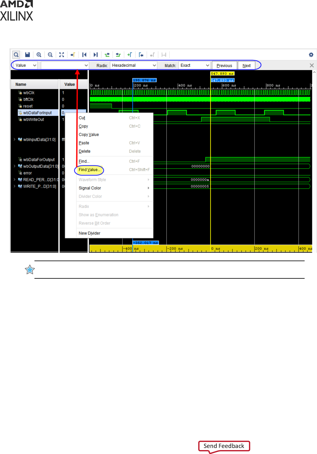
Figure 27: Find Value Option and Find Toolbar
IMPORTANT! This search feature supports only scalar and vector (1-D) wave objects of a “logic” type.
Logic types include 2-state and 4-state types of Verilog/SystemVerilog and bit and std_logic of VHDL.
To perform the search:
1. In the Name column, select one or more design wave objects (wave objects that have
waveforms).
2. Right-click one of the selected wave objects in either the Name column or Value column and
choose the Find Value opon to acvate the Find Toolbar.
3. On the Find Toolbar, choose a radix for your search value from the Radix drop down list. The
search feature supports the following radixes:
• Binary
• Hexadecimal
• Octal
• Unsigned Decimal
• Signed Decimal
Chapter 5: Analyzing Simulation Waveforms with Vivado Simulator
UG900 (v2022.1) April 21, 2022 www.xilinx.com
Vivado Design Suite User Guide: Logic Simulation 97
4. In the blank text box on the Find Toolbar, enter a value paern consisng of a string of digits
valid for the radix you chose. Valid digits include numeric digits, VHDL MVL 9 literals (U, X, 0,
1, Z, W, L, H, -), and Verilog literals (0, 1, x, z).
Note: If you enter an invalid digit, the text box turns red, and an error message appears at the right side
of the toolbar. The set of valid numeric digits depends on the radix. For example, if you chose the
Octal radix, numeric digits are those between 0 and 7. Numeric digits for hexadecimal include 0
through 9 and A through F (or a through f). You may enter the special digit '.' to specify a match with
any digit value. For example, the Octal value paern “12.4” matches occurrences of 1234, 1204, and
12X4 encountered in the waveform.
5. Choose a match style from the following opons in the Match drop down list:
• Exact: Waveform values must contain the same number of digits as in the value paern to
be considered a match. For example, a value paern of "1234" matches occurrences of
1234 encountered in the waveform but not 123 or 12345.
TIP: With the Exact match style you may omit leading zeros from the value paern. For example,
to nd the value 0023 in the waveform, you may specify a value paern of “0023” or simply “23.”
• Beginning: Any waveform value whose beginning digits match the value paern is
considered a match. For example, a value paern of “1234” matches occurrences of 1234
and 12345 encountered in the waveform but not 1235 or 123. This opon is available
only for radixes binary, octal, and hexadecimal.
• End: Any waveform value whose ending digits match the value paern is considered a
match. For example, a value paern of “1234” matches occurrences of 1234 and 91234
encountered in the waveform but not 1235 or 234. This opon is available only for radixes
binary, octal, and hexadecimal.
• Click the Next buon or press the Enter key to move the main cursor forward to the
nearest match, or click the Previous buon to move the main cursor backward to the
nearest match. With mulple wave objects selected, the cursor stops on the nearest
match of any of the selected wave objects.
TIP: If there are no matches in the requested direcon, the cursor remains staonary and a “Value
not found” message appears on the right side of the toolbar.
Analyzing AXI Interface Transactions
If you compose your design as a block design using the Vivado IP integrator, when you launch
the Vivado simulator, Vivado automacally imports the AMBA
®
AXI interfaces from your design
into the Vivado simulator as protocol instances to be viewed in the wave window. Once added to
the wave window, a protocol instance of an AXI interface shows you the data transacons
occurring on that interface during simulaon.
Chapter 5: Analyzing Simulation Waveforms with Vivado Simulator
UG900 (v2022.1) April 21, 2022 www.xilinx.com
Vivado Design Suite User Guide: Logic Simulation 98

Understanding Protocol Instances
An AXI interface consists of a standard set of logic signals as dened by Arm
®
in the AMBA
®
AXI
and ACE Protocol Specicaon and AMBA
®
4 AXI4-Stream Protocol Specicaon. These signals
convey the data transacons encoded as logic events as described by the specicaon. The
Vivado simulator makes those signals available for viewing directly in the wave viewer, however,
it can be dicult to visualize what transacons are happening from the signals alone.
To make it easier to view the transacons, the Vivado simulator provides a feature that analyzes
the signal acvity and produces new signals that summarize the acvity at the transacon level.
This process is called as protocol analysis. For each AXI interface the Vivado simulator creates a
new design object called a protocol instance that represents the AXI interface and the inputs and
outputs of protocol analysis. The protocol instance typically resides in the same scope as its input
signals.
Using the IP Integrator to Mark an AXI Interface to View in the
Vivado Simulator
The Vivado IP integrator provides a feature for idenfying AXI interfaces to display in the Vivado
simulator's wave viewer directly from the block design window. Perform the following steps to
mark an AXI interface for viewing in the Vivado simulator:
1. Locate the AXI interface you want to view.
2. Right-click the corresponding net connecon (orange line as shown in the following gure).
3. Click Mark Simulaon.
Note: Mark Simulaon opon can only be applied on an AXI interface.
4. Repeat steps 1-3 to mark addional interfaces.
5. Click Clear Simulaon opon to clear a marked AXI interface.
Note: Clear Simulaon opon is available only when an AXI interface is marked.
6. Launch the Vivado simulator. Save the block design if prompted.
When the Vivado simulator starts, the interfaces you marked appear in the Wave window. If
the Vivado project is customized to open a wave conguraon automacally, the marked
interfaces are added to the wave conguraon if not already present. If the Vivado project is
not customized to open a wave conguraon, the Vivado simulator creates a default wave
conguraon containing the marked interfaces in lieu of the usual top-level HDL signal list.
Chapter 5: Analyzing Simulation Waveforms with Vivado Simulator
UG900 (v2022.1) April 21, 2022 www.xilinx.com
Vivado Design Suite User Guide: Logic Simulation 99
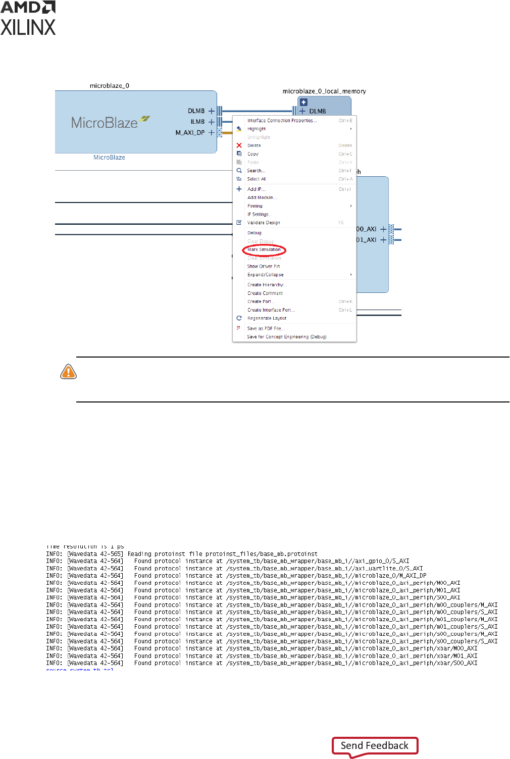
CAUTION! Some AXI interfaces which are internal to an AXI interconnect may not display correctly in
the wave viewer depending on the conguraon of the interconnect. It is recommended that you mark
interfaces only on the boundary of an interconnect.
Finding Protocol Instances in the Vivado Simulator
When the Vivado simulator launches, it scans the design and its input les to locate protocol
instances. The results of the scan appear in the Tcl console near the top of the simulator output
as shown in the following gure. You can copy a protocol instance path from the Tcl console and
paste it into a Tcl command.
Figure 28: Protocol Instances Identified in the Tcl Console
Chapter 5: Analyzing Simulation Waveforms with Vivado Simulator
UG900 (v2022.1) April 21, 2022 www.xilinx.com
Vivado Design Suite User Guide: Logic Simulation 100
Finding Protocol Instances in the Objects Window
Protocol instance objects appear in the Objects window in the scope containing the
corresponding AXI interface signals. Perform the following steps to nd a protocol instance using
the Scope window:
1. In the Scope window, select the scope containing AXI interface signals.
Note: The scope hierarchy roughly matches with your block design.
2. Locate the protocol instance for an AXI interface of a block in your block design. Select the
scope name that matches with the instance name of your block.
Perform the following steps to nd a protocol instance using the Objects window:
1. In the Objects window scroll to the boom of the list.
2. Locate the protocol instance name that matches with the port name of the AXI interface in
your block design. AXI port names usually end with _AXI and are frequently M_AXI or
S_AXI.
TIP: Protocol instances have a port mode of Internal Signal. To facilitate searching for protocol
instances in the Objects window, you can hide all objects except the Internal Signal object. Click the
gear icon, deselect the Select All check box and select the Internal Signal check box. To restore the
Objects window select the Select All check box.
Finding Protocol Instances Using a Tcl Command
Protocol instance objects have a Tcl type eld of proto_inst. You can use the get_objects
Tcl command to locate protocol instances in or under a specic scope.
Use the Following Command to Locate All Protocol Instances in the Design:
get_objects /* -r -filter {type==proto_inst}
Use the Following Command to Locate All Protocol Instances in a Scope:
get_objects <Design scope hierarchy>/* -filter {type==proto_inst}
Use the Following Command to Locate All Protocol Instances in or under a Scope:
get_objects /system_tb/base_mb_wrapper/base_mb_i/* -r -filter
{type==proto_inst}
Chapter 5: Analyzing Simulation Waveforms with Vivado Simulator
UG900 (v2022.1) April 21, 2022 www.xilinx.com
Vivado Design Suite User Guide: Logic Simulation 101
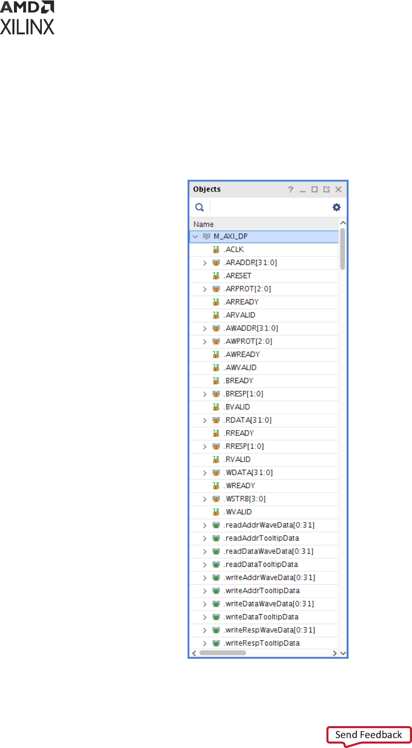
Protocol Instance in the Objects Window
In the Objects window, a protocol instance appears as an aggregate design object that has the
same name as the port name of the AXI interface seen in the block design. Click the arrow
expand buon to view the inputs and outputs of protocol analysis for the protocol instance as
shown in the following gure for a protocol instance named M_AXI_DP.
Figure 29: Protocol Instance in the Objects Window
Chapter 5: Analyzing Simulation Waveforms with Vivado Simulator
UG900 (v2022.1) April 21, 2022 www.xilinx.com
Vivado Design Suite User Guide: Logic Simulation 102
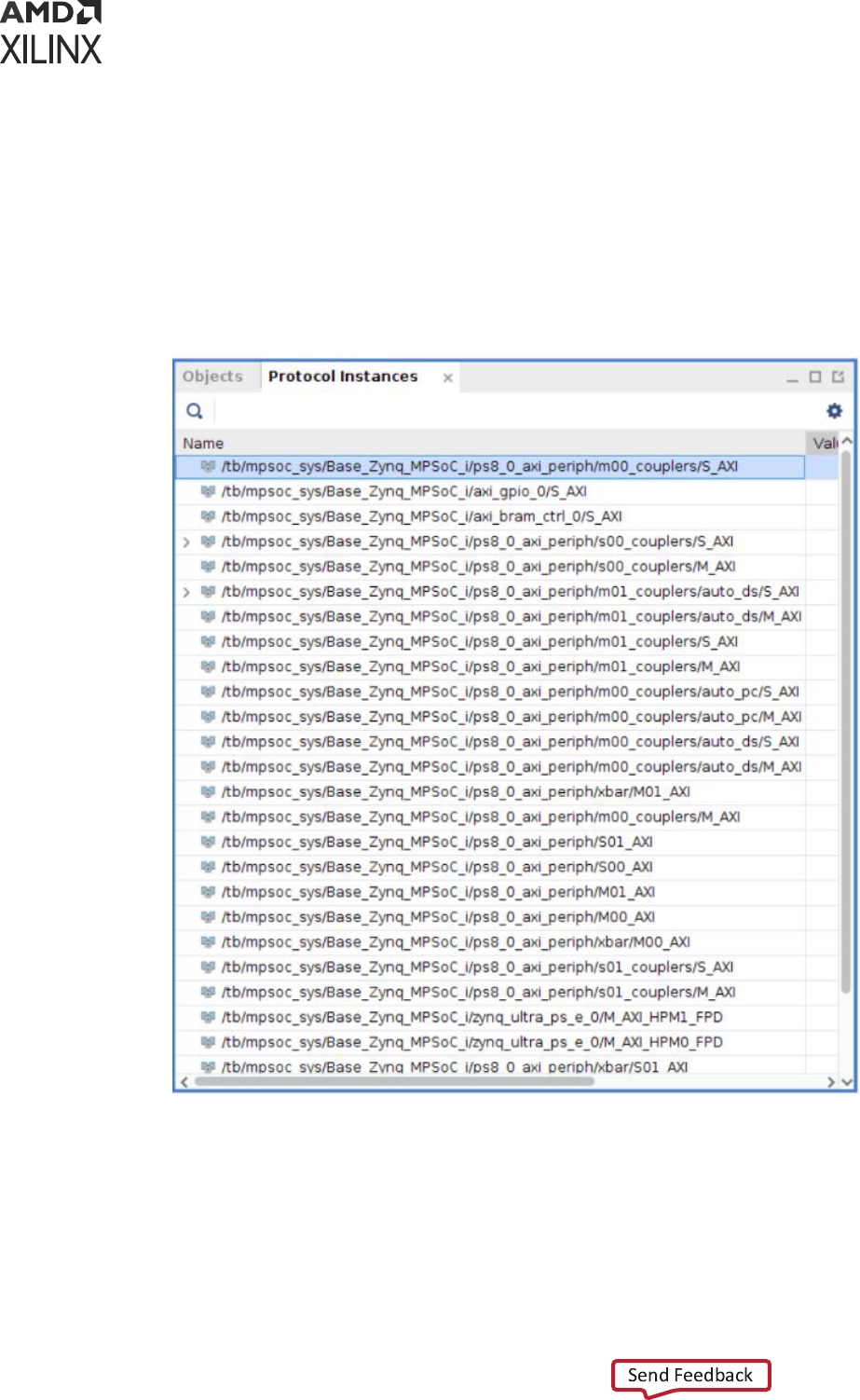
Note: To opmize computer resources, the protocol instance does not display its child objects unl the
protocol instance is added to the wave window for the rst me.
• Protocol Instances Window:
The protocol instances window contains the complete protocol instance list present in a given
design. It has an absolute path to the protocol instance to ensure that an instance with same
name can be dierenated based on the path.
Figure 30: Protocol Instances Window
• Protocol Instance Inputs:
Chapter 5: Analyzing Simulation Waveforms with Vivado Simulator
UG900 (v2022.1) April 21, 2022 www.xilinx.com
Vivado Design Suite User Guide: Logic Simulation 103
The protocol instance input signals shown with an orange icon are the aliases of the AXI
signals from the HDL design. Hover over an input to see a tool p giving full path of the alias
as well as the full path of the actual (aliased) signal. From a protocol instance input you can
also jump the Scope and Objects window to the actual signal. Perform the following steps to
go to the actual signal of a protocol instance input:
1. To view all signal types in the Objects window, click the gear icon and select the Check All
check box.
2. Right click the protocol instance input.
3. Select Go To Actual.
TIP: If you would like to save the protocol instance input signals in a wave conguraon (WCFG) le, add
the actual signals of the input signals instead. Because, the protocol instance inputs and outputs are
created only aer a WCFG le is loaded, your saved inputs will be missing from the wave conguraon.
The protocol instance outputs cannot be saved in a WCFG le.
• Protocol Instance Outputs:
The protocol instance outputs are shown with a green O icon. These are special signals of the
protocol instance that have no counterparts in the HDL design. The output signals produce
events meaningful only to the wave viewer for displaying transacons.
CAUTION!
The set of protocol instance output signals and their contents are subject to change from one
Vivado release to the next. It is recommended not to depend on the specic behavior of protocol instance
output signals when scripng using Tcl.
Adding Protocol Instances to the Wave Window
You can add any protocol instance present in the design to the wave window. Adding a protocol
instance to the wave window causes the Vivado simulator to run protocol analysis on the
protocol instance inputs starng from the simulaon me 0 regardless of how much simulaon
me has already elapsed. As protocol analysis ulizes the waveform database (WDB), inputs of
all protocol instances are always traced in the waveform database even if you have not requested
tracing of the inputs or added the protocol instance to the wave window.
In addion to marking an AXI interface in your IP integrator block design as described in Using
the IP Integrator to Mark an AXI Interface to View in the Vivado Simulator secon, you can add a
protocol instance to the wave window using the Objects window or a Tcl command.
IMPORTANT!
Protocol instances may use more computer resources, it is recommended that you add just
the protocol instances you currently need. You can always add addional protocol instances at a later me
during the simulaon without missing the data.
Perform the following steps to add a protocol instance to the Wave window using the Objects
window:
Chapter 5: Analyzing Simulation Waveforms with Vivado Simulator
UG900 (v2022.1) April 21, 2022 www.xilinx.com
Vivado Design Suite User Guide: Logic Simulation 104

1. To locate the protocol instance in the Objects window, see the steps described in the secon
Finding Protocol Instances in the Objects Window.
2. Add the protocol instance to the Wave window by the following two ways:
a. Right click the protocol instance and choose Add to Wave.
b. Drag and drop the protocol instance to the Name column of the Wave window.
Perform the following steps to add a protocol instance to the Wave window using a Tcl
command:
1. To locate the protocol instance in the Objects window, see the steps described in the secon
Finding Protocol Instances in the Vivado Simulator.
2. Copy the protocol instance path to the clipboard:
a. If you have located the protocol instance in the Objects window, le click the protocol
instance to select it and copy the protocol instance path.
b. If you have located the protocol instance in the Tcl console, use your mouse to select the
protocol instance path and copy it.
c. If you have located the protocol instance using the get_objects Tcl command, use your
mouse to select the text of the protocol instance path in the Tcl console and copy it.
Alternavely, you can get objects together as described in the following secon.
3. Type add_wave and paste the protocol instance name.
TIP:
If your protocol instance path contains special characters, surround the path with double braces. For
example,
add_wave {{path}}
.
Using get_objects Programmatically
When you use the get_objects Tcl command as described in Finding Protocol Instances Using
a Tcl Command, the command returns the protocol instances as a Tcl list. You can store the list in
a Tcl variable:
set p [get_objects -r /* -filter {type==proto_inst}]
and use the list with the add_wave Tcl command to add all the protocol instances in the list:
add_wave $p
or a specic protocol instance from the list using the built-in lindex command as shown in the
following example that adds the rst protocol instance of the list:
add_wave [lindex $p 0]
Chapter 5: Analyzing Simulation Waveforms with Vivado Simulator
UG900 (v2022.1) April 21, 2022 www.xilinx.com
Vivado Design Suite User Guide: Logic Simulation 105
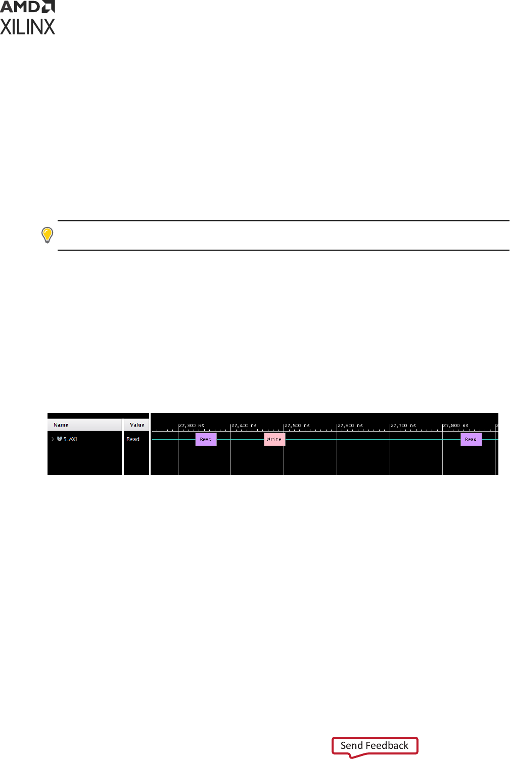
Analyzing Protocol Instances in the Wave Window
This secon describes the waveform features common to all interface types. See the following
protocol specic secons for more informaon about a specic interface type (AXI Memory
Mapped or AXI4 Stream).
Understanding Protocol Instances in the Wave Window
When you add a protocol instance to the wave window, the Vivado simulator creates a hierarchy
of wave objects to represent the protocol instance. You cannot change the structure of the
hierarchy. The type of AXI interface determines the hierarchy.
TIP: You may need to view the protocol instance input signals not included in the wave object hierarchy.
While you cannot add the signals into the hierarchy, you can add them before or aer the hierarchy.
Understanding Transaction Waveforms
Transacon waveforms dier from other types of waveforms. A transacon waveform displays
periods of acvity and inacvity of some aspect of the simulated design in contrast with
displaying value changes of a signal over me. The following gure shows an example of a
transacon waveform. A thin line indicates periods of inacvity, while the rectangles represent
periods of acvity which are generally called transacon bars. The example in the gure shows
three transacon bars.
Figure 31: Transaction Waveform Display
As shown in the following gure, the transacon waveform displays a gray bar with the text
Loading while protocol analysis is performed on the inputs of the protocol instance. As the
protocol analysis progresses, the gray bars shrink to reveal newly processed transacon data.
Chapter 5: Analyzing Simulation Waveforms with Vivado Simulator
UG900 (v2022.1) April 21, 2022 www.xilinx.com
Vivado Design Suite User Guide: Logic Simulation 106
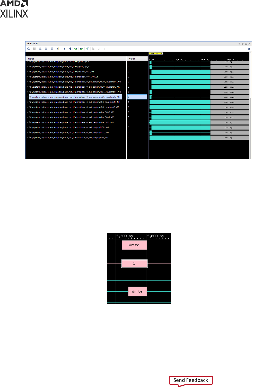
Figure 32: Transaction Waveforms Showing Incomplete Protocol Analysis
Using Transaction Bars
Selecting Transaction Bars
Place your cursor on a transacon bar and le click to select the transacon bar which is
highlighted with a double border as shown in the following gure:
Figure 33: A Selected Transaction Bar
If the selected transacon bar is a member of a group of related transacon bars, arrows appear
called associaons connecng the related transacon bars. The rest of the objects in the wave
window appear dim to highlight the group of transacon bars. The following gure shows a
selected transacon bar and its related transacon bars connected with associaons.
Chapter 5: Analyzing Simulation Waveforms with Vivado Simulator
UG900 (v2022.1) April 21, 2022 www.xilinx.com
Vivado Design Suite User Guide: Logic Simulation 107
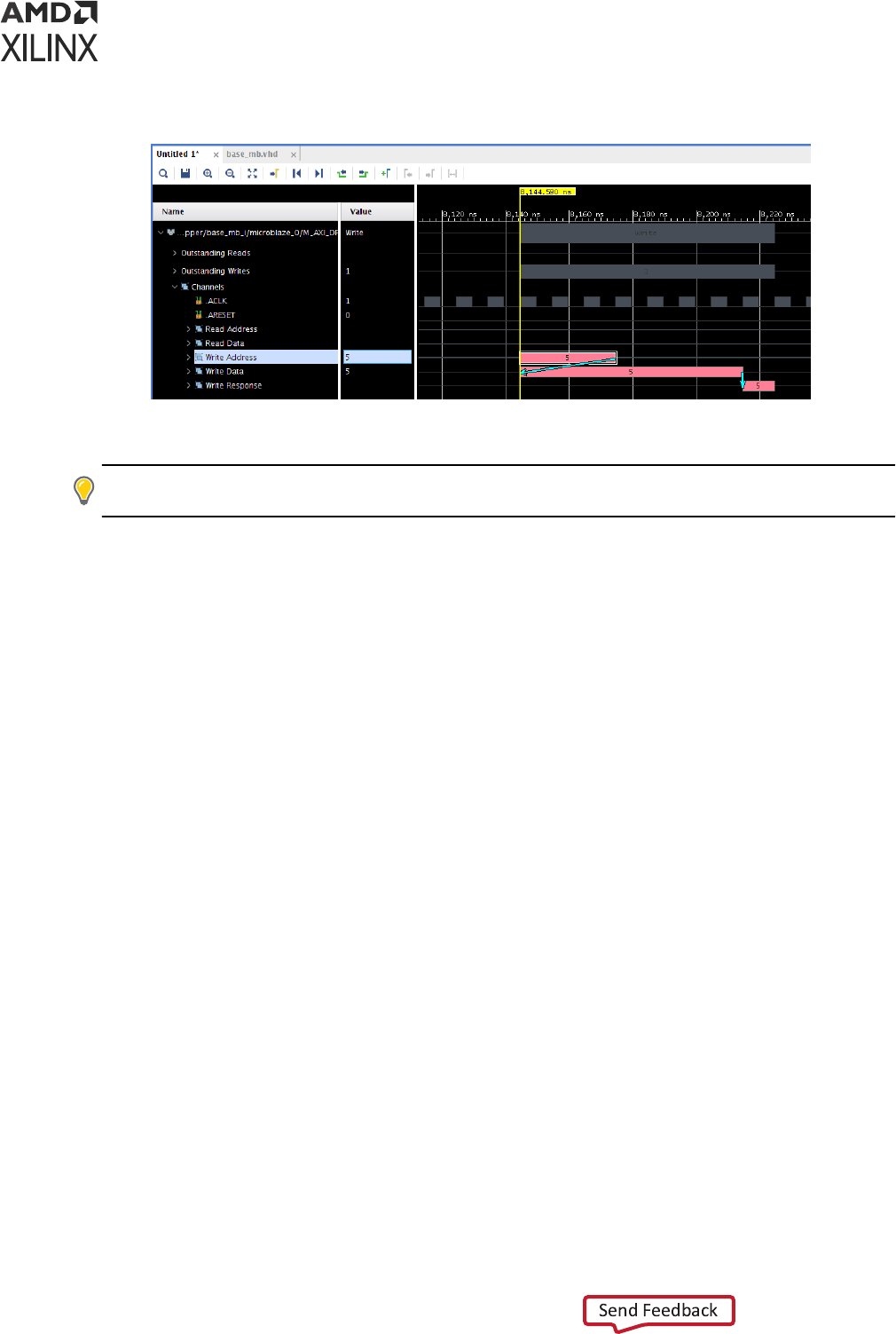
Figure 34: Transaction Bars with Associations
Press the Esc key to clear the transacon bar selecon.
TIP: To reposion the main cursor within a transacon waveform, hold the Ctrl key and le click at the
desired cursor me.
Navigation Transactions Using Associations
When you click on one end of an associaon, the selecon moves to the transacon bar at the
other end of the associaon, and the wave window scrolls so that the other end is in view.
Note: The wave window may not scroll if the other end is already in view.
Tool Tips
When you hover over a transacon bar or an associaon using your mouse, a tool p displaying
extra informaon about the transacon bar or associaon may appear depending on the type of
protocol instance interface.
Analyzing AXI Memory-Mapped (AXI-MM) Interfaces
This secon describes the transacon viewing features specic to AXI-MM protocol instances. A
protocol instance of an AXI-MM interface appears in the wave window with a wave object
hierarchy as shown in the following gure.
Chapter 5: Analyzing Simulation Waveforms with Vivado Simulator
UG900 (v2022.1) April 21, 2022 www.xilinx.com
Vivado Design Suite User Guide: Logic Simulation 108
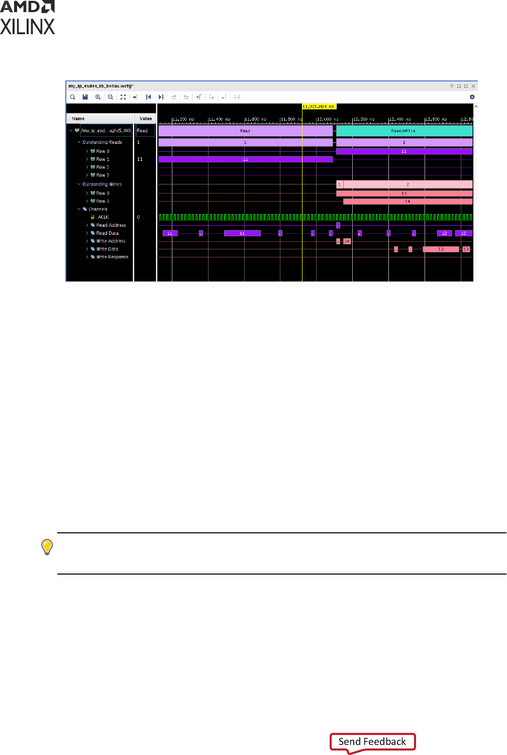
Figure 35: AXI-MM Interface
Understanding the Top Summary Row
The top of the wave object hierarchy of an AXI-MM protocol instance is the top summary row.
This transacon waveform shows the overall read and write acvity of an AXI interface based on
the following rules:
• If one or more AXI read transacons are in progress, the top summary shows a Read
transacon bar in purple color.
• If one or more AXI write transacons are in progress, the top summary shows a Write
transacon bar in pink color.
• If one or more of AXI read and write transacons are in progress, the top summary shows
Read/Write transacon bar in teal color.
An AXI transacon is an abstract concept not to be confused with the graphical transacon bar.
It is a complete data exchange carried out using AXI signaling including the Address, Data, and
oponally Response phases.
TIP:
For performance reasons, the wave viewer does not display the transacon bars in dierent colors
when zoomed out. Instead, it displays all transacon bars in teal color. You need to zoom in to disnguish
between read and write transacons.
Chapter 5: Analyzing Simulation Waveforms with Vivado Simulator
UG900 (v2022.1) April 21, 2022 www.xilinx.com
Vivado Design Suite User Guide: Logic Simulation 109
Understanding the Outstanding Reads and Outstanding Writes Rows
There are a group of outstanding AXI read transacons and a group of write transacons located
under the top of the wave object hierarchy of an AXI-MM protocol instance. An AXI transacon
is known as outstanding if the interface master has raised A*VALID or WVALID but the last data
phase or oponally response phase has not yet completed. The outstanding reads row shows the
current count of outstanding AXI read transacons or is inacve (shown as a thin line) to indicate
zero outstanding AXI read transacons. Similarly, the outstanding writes row shows the current
count of outstanding AXI write transacons or is inacve to indicate zero outstanding AXI write
transacons.
Understanding the Transaction Summary Rows
There is a set of transacon summary rows under each outstanding read and write row labeled as
Row <n>, where <n> is an integer. A transacon summary is a transacon bar that depicts a
single AXI transacon starng at the rst phase and ending at the last phase of an AXI
transacon. The assignment of a transacon summary to a specic numbered row conveys no
special meaning. Instead, it prevents overlapping of mulple outstanding AXI transacons in the
same row.
TIP: The number of transacon summary rows can increase as simulaon progresses. For performance
reasons, the wave window updates the rows only when protocol analysis is complete. To see the latest
state of the rows during simulaon without waing for the enre simulaon to complete, you can pause
the simulaon and allow the Loading bars to disappear.
Each transacon summary is labeled with a sequence number. The rst AXI transacon has a
sequence number of 1, the second AXI transacon has a sequence number of 2, and so forth.
The progression of sequence numbers for reads and writes are separate from each other and
from the AXI transacons of all other protocol instances. For example, a parcular protocol
instance can have an AXI read transacon with the sequence number 16 and a separate AXI
write transacon with the sequence number 16.
Understanding Channel Rows
The channels wave object group is collapsed by default. When you expand the group, you see
logic signals for the AXI interface clock and reset (if present) and one transacon row for each
AXI channel present in the interface.
Note: Not all ve channels are necessarily present in an AXI interface. For read only interfaces, the write
channels are absent. For write only interfaces, the read channels are absent. Some AXI interfaces that
employ the write channels may omit the response channel if the AXI master has no use of the response
informaon.
Chapter 5: Analyzing Simulation Waveforms with Vivado Simulator
UG900 (v2022.1) April 21, 2022 www.xilinx.com
Vivado Design Suite User Guide: Logic Simulation 110
Each channel row shows a transacon bar summarizing individual handshakes of that AXI
channel from VALID to READY, except that the mulple conguous data beats of the same AXI
transacon appear as a single transacon bar. To visually e all channel transacon bars of an
AXI transacon together, each channel transacon bar is tagged with the same sequence number
as the corresponding transacon summary. You can expand the channel row to show key AXI
signals for that channel.
TIP: You may need to view protocol instance input signals not included in the wave object hierarchy. While
you cannot add the signals into the hierarchy, you can add them before or aer the hierarchy.
TIP: You may noce that channel transacon bars appear up to one clock cycle aer the corresponding
AXI signal event. The AXI protocol analyzers consider AXI signal events that occur on or aer a posive
clock edge to take eect at the following posive clock edge.
When you hover over any channel transacon bar, associaon, or transacon summary using
your mouse, a tool p appears showing the values of the informaonal AXI address channel
signals from the address phase of the AXI transacon.
Note: Oponal AXI address channel signals which are absent from the interface are omied from the tool
p.
When you select a channel transacon bar, associaons appear for all channel transacon bars
parcipang in the same AXI transacon as the selected transacon bar. You can click the tails of
the associaon arrows to follow the progress of the AXI transacon from address phase through
response phase. The chain of associaons always begins with the address phase transacon even
if the data phase precedes the address phase.
Error Conditions
If there is a handshaking error on the interface, you may see a sequence number on a channel
transacon consisng of a string of all 9s. This sequence number indicates that the data and/or
response phases could not be matched with an address and/or data phase. Common causes are
mismatched read/write ID tags and the protocol analyzer being held in reset (ARESET or
ARESETn signal acve) while the AXI phases are in progress.
CAUTION!
Because certain conguraons of an AXI interconnect are opmized for performance rather
than transacon debugging, AXI interfaces internal to an AXI interconnect may respect a dierent reset
signal than the one connected to the interface causing transacon errors in the wave viewer. If you observe
transacon errors on the interface, it is recommended that you monitor interfaces on the outside of the
interconnect instead.
Analyzing AXI4-Stream (AXI-S) Interfaces
This secon describes the transacon viewing features specic to AXI-Stream protocol instances.
A protocol instance of an AXI-S interface appears in the wave window with a wave object
hierarchy as shown in the following gure.
Chapter 5: Analyzing Simulation Waveforms with Vivado Simulator
UG900 (v2022.1) April 21, 2022 www.xilinx.com
Vivado Design Suite User Guide: Logic Simulation 111
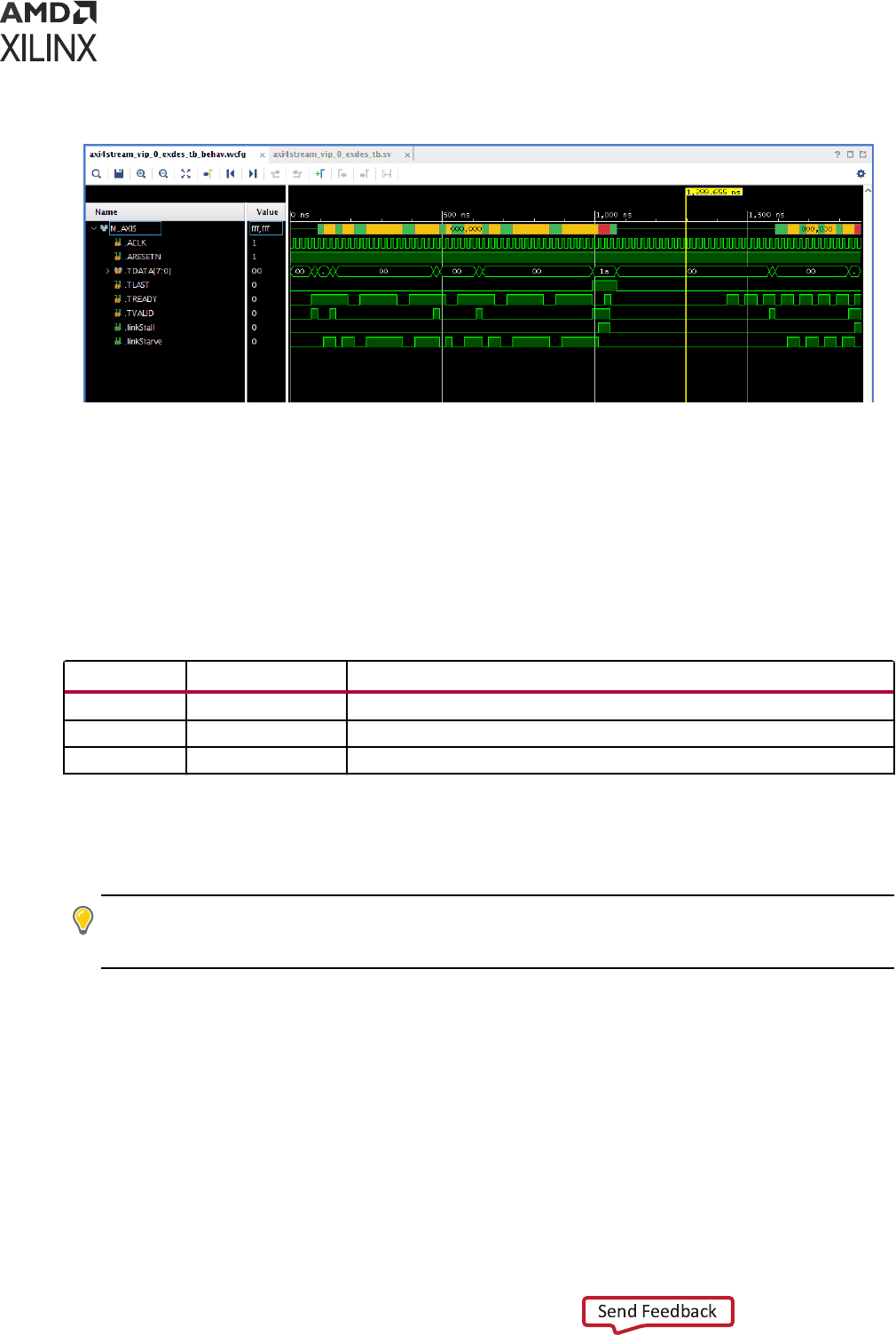
Figure 36: AXI-Stream (AXI-S) Interface
The wave object hierarchy of an AXI-S interface contains only one transacon row which is at
the top of the hierarchy. Each transacon bar in the row corresponds to one complete AXI
transacon. The text on the transacon consists of the stream idener from AXI signal TID and
the coarse roung informaon from AXI signal TDEST.
The transacon bar contains color coded stripes to indicate the status of an AXI transacon as
described in the following table.
Table 12: AXI Transaction Status
Color Status Description
Green Normal Data is streaming normally.
Yellow Starve Slave is waiting for data from the master.
Red Stall Master is producing data faster than slave can consume it.
Under the top transacon row, the wave object hierarchy contains some of the key AXI signals
plus stall and starve status signals to indicate stall and starve condions. The status signals
provide the same informaon as the color stripes do in the transacon row.
TIP:
You may noce that the channel transacon bars appear up to one clock cycle aer the
corresponding AXI signal event. The AXI protocol analyzers consider AXI signal events that occur on or
aer a posive clock edge to take eect at the following posive clock edge.
Error Conditions
A handshaking error produces an error transacon with the text containing all Fs.
Chapter 5: Analyzing Simulation Waveforms with Vivado Simulator
UG900 (v2022.1) April 21, 2022 www.xilinx.com
Vivado Design Suite User Guide: Logic Simulation 112

Chapter 6
Debugging a Design with Vivado
Simulator
The Vivado
®
Design Suite simulator provides you with the ability to:
• Examine source code
• Set breakpoints and run simulaon unl a breakpoint is reached
• Step over secons of code
• Force waveform objects to specic values
This chapter describes debugging methods and includes Tcl commands that are valuable in the
debug process. There is also a ow descripon on debugging with third-party simulators.
Debugging at the Source Level
You can debug your HDL source code to track down unexpected behavior in the design.
Debugging is accomplished through controlled execuon of the source code to determine where
issues might be occurring. Available strategies for debugging are:
• Step through the code line by line: For any design at any point in development, you can use
the step command to debug your HDL source code one line at a me to verify that the
design is working as expected. Aer each line of code, run the step command again to
connue the analysis. For more informaon, see Stepping Through a Simulaon.
• Set breakpoints on the specic lines of HDL code, and run the simulaon unl a breakpoint is
reached: In larger designs, it can be cumbersome to stop aer each line of HDL source code is
run. Breakpoints can be set at any predetermined points in your HDL source code, and the
simulaon is run (either from the beginning of the test bench or from where you currently are
in the design) and stops are made at each breakpoint. You can use the Step, Run All, or Run
For command to advance the simulaon aer a stop. For more informaon, see the secon,
Using Breakpoints, below.
• Set condions. The tools evaluate each condion and execute Tcl commands when the
condion is true. Use the Tcl command:
add_condition <condition> <instruction>
Chapter 6: Debugging a Design with Vivado Simulator
UG900 (v2022.1) April 21, 2022 www.xilinx.com
Vivado Design Suite User Guide: Logic Simulation 113

See Adding Condions for more informaon.
Stepping Through a Simulation
You can use the step command, which executes your HDL source code one line of source code
at a me, to verify that the design is working as expected.
The line of code is highlighted and an arrow points to the currently execung line of code.
You can also create breakpoints for addional stops while stepping through your simulaon. For
more informaon on debugging strategies in the simulator, seethe secon, Using Breakpoints,
below.
1. To step through a simulaon:
• From the current running me, select Run > Step, or click the Step buon .
The HDL associated with the top design unit opens as a new view in the Wave window.
• From the start (0 ns), restart the simulaon. Use the Restart command to reset me to the
beginning of the test bench. See Chapter 4: Simulang with Vivado Simulator.
2. In the waveform conguraon window, right-click the waveform or HDL tab and select Tile
Horizontally see the waveform and the HDL code simultaneously.
3. Repeat the Step acon unl debugging is complete.
As each line is executed, you can see the arrow moving down the code. If the simulator is
execung lines in another le, the new le opens, and the arrow steps through the code. It is
common in most simulaons for mulple les to be opened when running the Step command.
The Tcl Console also indicates how far along the HDL code the step command has progressed.
Using Breakpoints
A breakpoint is a user-determined stopping point in the source code that you can use for
debugging the design.
TIP:
Breakpoints are parcularly helpful when debugging larger designs for which debugging with the Step
command (stopping the simulaon for every line of code) might be too cumbersome and me consuming.
You can set breakpoints in executable lines in your HDL le so you can run your code
connuously unl the simulator encounters the breakpoint.
Note: You can set breakpoints on lines with executable code only. If you place a breakpoint on a line of
code that is not executable, the breakpoint is not added.
1. Run a simulaon.
Chapter 6: Debugging a Design with Vivado Simulator
UG900 (v2022.1) April 21, 2022 www.xilinx.com
Vivado Design Suite User Guide: Logic Simulation 114

2. Go to your source le and click the hollow circle to the le of the source line of interest.
A red dot conrms the breakpoint is set correctly.
Aer the procedure completes, a simulaon breakpoint buon opens next to the line of code.
Type the Tcl Command: add_bp <file_name> <line_number>
This command adds a breakpoint at <line_number> of <file_name>. See the Vivado
Design Suite help or the Vivado Design Suite Tcl Command Reference Guide (UG835) for
command usage.
Open the HDL source le.
3. Set breakpoints on executable lines in the HDL source le.
4. Repeat steps 1 and 2 unl all breakpoints are set.
5. Run the simulaon, using a Run opon:
• To run from the beginning, use the Run > Restart command.
• Use the Run > Run All or Run > Run For command.
The simulaon runs unl a breakpoint is reached, then stops.
The HDL source le displays an arrow, indicang the breakpoint stopping point.
6. Repeat Step 4 to advance the simulaon, breakpoint by breakpoint, unl you are sased
with the results.
A controlled simulaon runs, stopping at each breakpoint set in your HDL source les.
During design debugging, you can also run the Run > Step command to advance the
simulaon line by line to debug the design at a more detailed level.
You can delete a single breakpoint or all breakpoints from your HDL source code.
To delete a single breakpoint, click the Breakpoint buon
.
To remove all breakpoints, either select Run> Delete All Breakpoints or click the Delete All
Breakpoints buon .
To delete all breakpoints:
• Type the Tcl command remove_bps -all.
To get breakpoint informaon on the specied list of breakpoint objects:
• Type the Tcl command report_bps
Chapter 6: Debugging a Design with Vivado Simulator
UG900 (v2022.1) April 21, 2022 www.xilinx.com
Vivado Design Suite User Guide: Logic Simulation 115

Adding Conditions
To add breakpoints based on a condion and output a diagnosc message, use the following
commands:
add_condition <condition> <message>
Using the Vivado IDE BFT example design, to stop when the wbClk signal and the reset are
both acve-High, issue the following command at start of simulaon to print a diagnosc
message and pause simulaon when reset goes to 1 and wbClk goes to 1:
add_condition {reset == 1 && wbClk == 1} {puts "Reset went to high"; stop}
In the BFT example, the added condion causes the simulaon to pause at 5 ns when the
condion is met and "Reset went to high" is printed to the console. The simulator waits
for the next step or run command to resume simulaon.
-notrace Option
Normally, when you execute the add_condition command, the specied Tcl commands also
echo to the console, log le, and journal le. The -notrace switch causes those commands to
execute silently, suppressing the commands (but not their output) from appearing in those three
places.
For Example, If you execute the following example command:
puts 'Hello'
The normal behavior of the above command would be to emit the following output in the
console, log le, and journal le:
# puts ‘Hello’
Hello
When you execute -notrace switch, it would produce only the following output:
Hello
Pausing a Simulation
While running a simulaon for any length of me, you can pause a simulaon using the Break
command, which leaves the simulaon session open.
To pause a running simulaon, select Simulaon > Break or click the Break buon .
The simulator stops at the next executable HDL line. The line at which the simulaon stopped is
displayed in the text editor.
Chapter 6: Debugging a Design with Vivado Simulator
UG900 (v2022.1) April 21, 2022 www.xilinx.com
Vivado Design Suite User Guide: Logic Simulation 116

Note: This behavior applies to designs that are compiled with the -debug <kind> switch.
Resume the simulaon any me using the Run All, Run, or Step commands. See Stepping
Through a Simulaon for more informaon.
Tracing the Execution of a Simulation
You can display a note on the Tcl console for every source line that the simulaon encounters
while running. This connuous display of encountered lines is called line tracing.
To turn on line tracing, use one of the following Tcl commands:
ltrace on
set_property line_tracing true [current_sim]
To turn o line tracing use one of the following Tcl commands:
ltrace off
set_property line_tracing false [current_sim]
You can display a note on the Tcl console for every process that the simulaon encounters while
running. This connuous display of encountered processes is called process tracing.
To turn on process tracing, use one of the following Tcl commands:
ptrace on
set_property process_tracing true [current_sim]
To turn o process tracing, use one of the following Tcl commands:
ptrace off
set_property process_tracing false [current_sim]
Forcing Objects to Specific Values
Using Force Commands
The Vivado simulator provides an interacve mechanism to force a signal, wire, or register to a
specied value at a specied me or period of me. You can also force values on objects to
change over a period of me.
TIP:
A 'force' is both an acon (that is, the overriding of HDL-dened behavior on a signal) and also a Tcl
rst-class object, something you can hold in a Tcl variable.
Chapter 6: Debugging a Design with Vivado Simulator
UG900 (v2022.1) April 21, 2022 www.xilinx.com
Vivado Design Suite User Guide: Logic Simulation 117
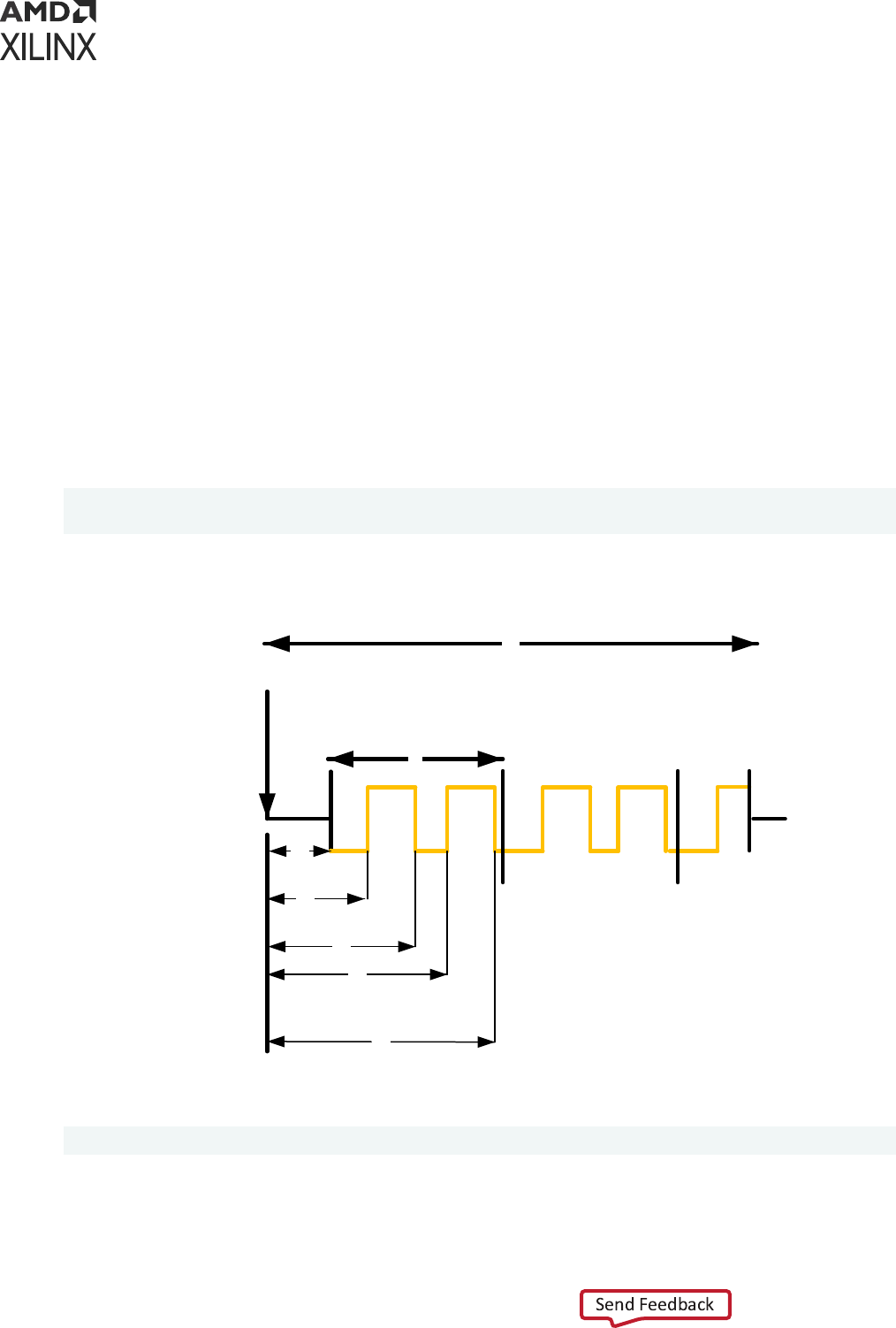
You can use force commands on an HDL signal to override the behavior for that signal as dened
in your HDL design. You might, for example, choose to override the behavior of a signal to:
• Supply a smulus to a test bench signal that the HDL test bench itself is not driving
• Correct a bad value temporarily during debugging (allowing you to connue analyzing a
problem)
The available force commands are:
• Force Constant
• Force Clock
• Remove Force
The following gure illustrates how the add_force funconality is applied given the following
command:
add_force mySig {0 t
1
} {1 t
2
} {0 t
3
} {1 t
4
} {0 t
5
} -repeat_every tr -
cancel_after t
c
Figure 37: Illustration of -add_force Functionality
tc
tr
t1
t2
t3
t4
t5
Current Time
You can get more detail on the command by typing the following in the Tcl Console:
add_force -help
Chapter 6: Debugging a Design with Vivado Simulator
UG900 (v2022.1) April 21, 2022 www.xilinx.com
Vivado Design Suite User Guide: Logic Simulation 118
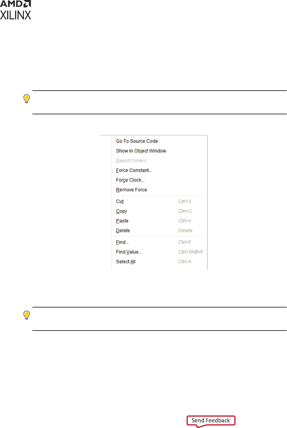
Force Constant
The Force Constant opon lets you x a signal to a constant value, overriding the assignments
made within the HDL code or another previously applied constant or clock force.
Force Constant and Force Clock are opons in the Objects or wave window right-click menu (as
shown in the following gure), or in the text editor (source code).
TIP: Double-click an item in the Objects, Sources, or Scope window to open it in the text editor. For
addional informaon about the text editor, see the Vivado Design Suite User Guide: Using the Vivado IDE
(UG893).
Figure 38: Force Options
The Force opons are disabled for the objects for which the Vivado simulator does not support
forcing. The type of object or limitaons in the Vivado simulator's modeling for those objects
may be the cause for not supporng such objects.
TIP:
To force a module or enty port whose Force opons are disabled, try forcing its connected actual
signal one scope level up. Use the
add_force
Tcl command (for example,
add_force myObj 0
) to
view the reason why the opons are disabled.
When you select the Force Constant opon, the Force Constant dialog box opens so you can
enter the relevant values, as shown in the following gure.
Chapter 6: Debugging a Design with Vivado Simulator
UG900 (v2022.1) April 21, 2022 www.xilinx.com
Vivado Design Suite User Guide: Logic Simulation 119
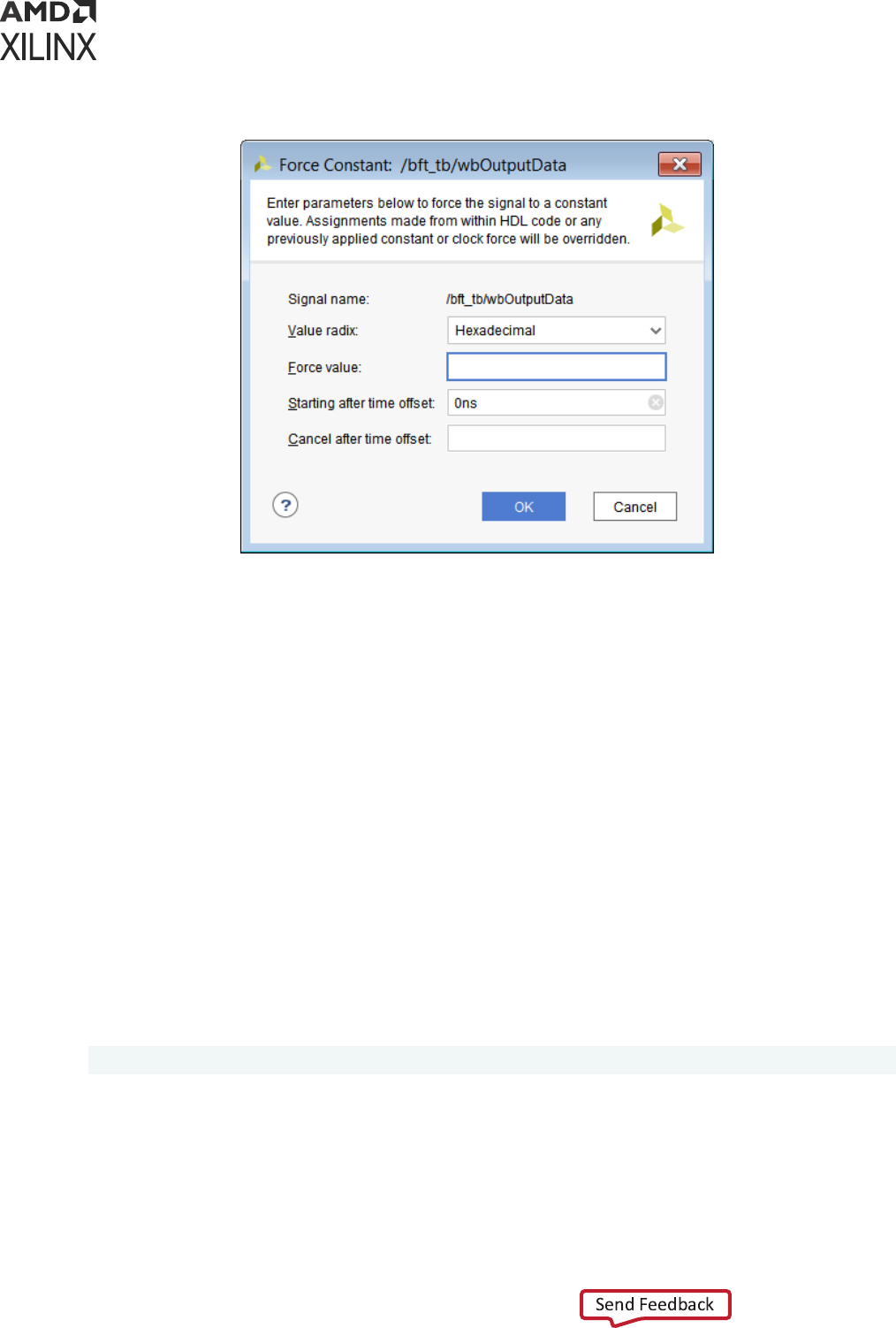
Figure 39: Force Constant Dialog Box
The following are Force Constant opon descripons:
• Signal name: Displays the default signal name, that is, the full path name of the selected
object.
• Value radix: Displays the current radix seng of the selected signal. You can choose one of
the supported radix types: Binary, Hexadecimal, Unsigned Decimal, Signed Decimal, Signed
Magnitude, Octal, and ASCII. The GUI then disallows entry of the values based on the Radix
seng. For example: if you choose Binary, no numerical values other than 0 and 1 are
allowed.
• Force value: Species a force constant value using the dened radix value. (For more
informaon about radixes, see Changing the Default Radix and Using Analog Waveforms.)
• Starng aer me oset: Starts aer the specied me. The default starng me is 0. Time
can be a string, such as 10 or 10 ns. When you enter a number without a unit, the Vivado
simulator uses the default (ns).
• Cancel aer me oset: Cancels aer the specied me. Time can be a string such as 10 or
10 ns. If you enter a number without a unit, the default simulaon me unit is used.
Tcl command:
add_force /testbench/TENSOUT 1 200 -cancel_after 500
Chapter 6: Debugging a Design with Vivado Simulator
UG900 (v2022.1) April 21, 2022 www.xilinx.com
Vivado Design Suite User Guide: Logic Simulation 120
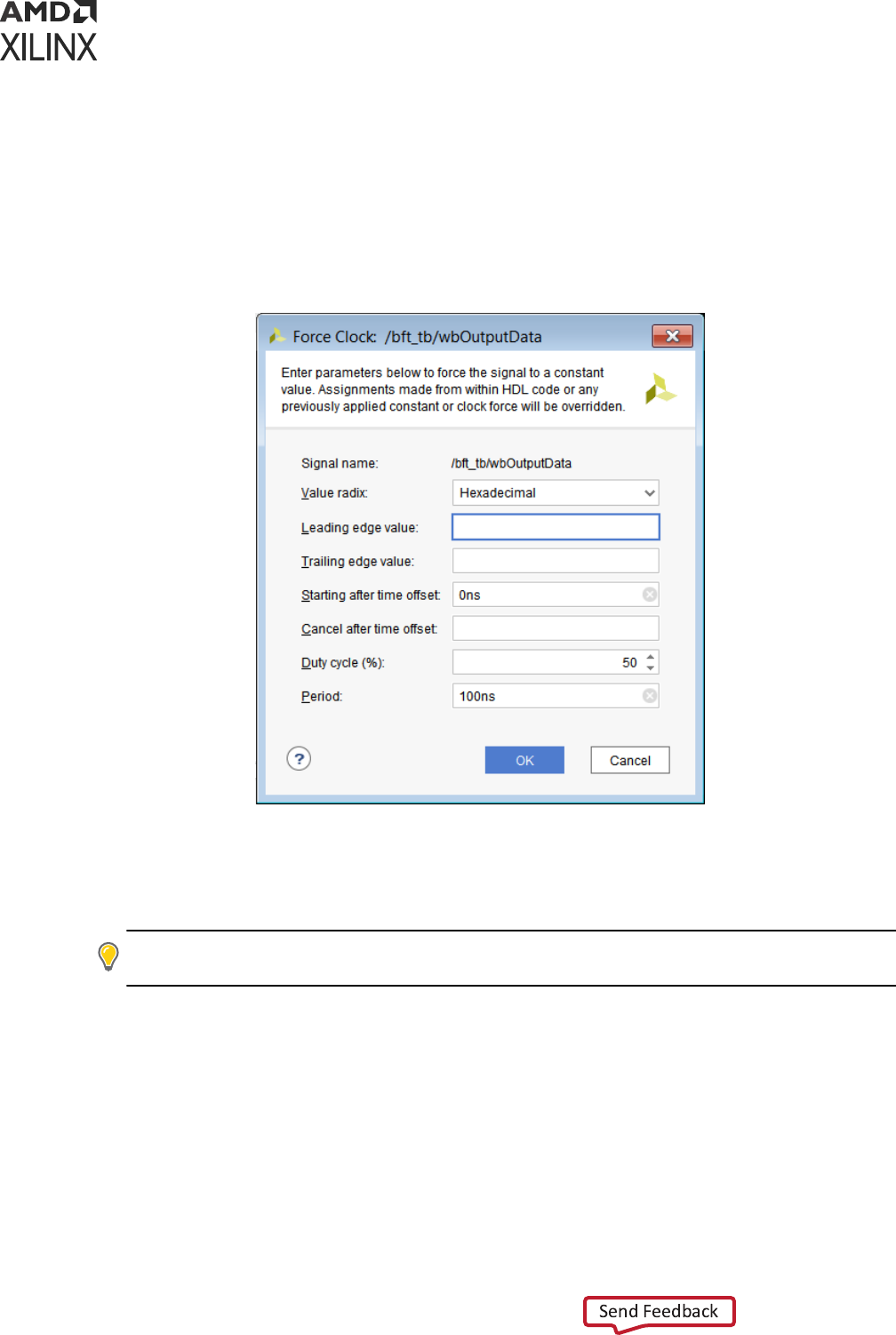
Force Clock
The Force Clock command lets you assign a signal a value that toggles at a specied rate
between two states, in the manner of a clock signal, for a specied length of me. When you
select the Force Clock opon in the Objects window menu, the Force Clock dialog box opens, as
shown in the following gure.
Figure 40: Force Clock Dialog Box
The
opons in the Force Clock dialog box are shown below.
• Signal name: Displays the default signal name; the full path name of the item selected in the
Objects window or waveform.
TIP: The Force Clock command can be applied to any signal (not just clock signals) to dene an
oscillang value.
• Value radix: Displays the current radix seng of the selected signal. Select one of the
displayed radix types from the drop-down menu: Binary, Hexadecimal, Unsigned Decimal,
Signed Decimal, Signed Magnitude, Octal, or ASCII.
• Leading edge value: Species the rst edge of the clock paern. The leading edge value uses
the radix dened in Value radix eld.
• Trailing edge value: Species the second edge of the clock paern. The trailing edge value
uses the radix dened in the Value radix eld.
Chapter 6: Debugging a Design with Vivado Simulator
UG900 (v2022.1) April 21, 2022 www.xilinx.com
Vivado Design Suite User Guide: Logic Simulation 121

• Starng aer me oset: Starts the force command aer the specied me from the current
simulaon. The default starng me is 0. Time can be a string, such as 10 or 10 ns. If you
enter a number without a unit, the Vivado simulator uses the default user unit.
• Cancel aer me oset: Cancels the force command aer the specied me from the current
simulaon me. Time can be a string, such as 10 or 10 ns. When you enter a number without
a unit, the Vivado simulator uses the default simulaon me unit.
• Duty cycle (%): Species the percentage of me that the clock pulse is in an acve state. The
acceptable value is a range from 0 to 100 (default is 50%).
• Period: Species the length of the clock pulse, dened as a me value. Time can be a string,
such as 10 or 10 ns.
Note: For more informaon about radixes, see Changing the Default Radix and Using Analog
Waveforms.
Example Tcl command:
add_force /testbench/TENSOUT -radix bin {0} {1} -repeat_every 10ns -
cancel_after 3us
Remove Force
Remove Force
To remove any specied force from an object use the following Tcl command:
remove_forces <force object>
remove_forces <HDL object>
Using Force in Batch Mode
The code examples below show how to force a signal to a specied value using the add_force
command. A simple verilog circuit is provided. The rst example shows the interacve use of the
add_force command and the second example shows the scripted use.
Example 1: Adding Force
The following code snippet is a Verilog circuit:
module bot(input in1, in2,output out1);
reg sel;
assign out1 = sel? in1: in2;
endmodule
module top;
reg in1, in2;
wire out1;
bot I1(in1, in2, out1);
initial
begin
#10 in1 = 1'b1; in2 = 1'b0;
Chapter 6: Debugging a Design with Vivado Simulator
UG900 (v2022.1) April 21, 2022 www.xilinx.com
Vivado Design Suite User Guide: Logic Simulation 122

#10 in1 = 1'b0; in2 = 1'b1;
end
initial
$monitor("out1 = %b\n", out1);
endmodule
You can invoke the following commands to observe the eect of add_force:
xelab -vlog tmp.v -debug all
xsim work.top
At the command prompt, type:
add_force /top/I1/sel 1
run 10
add_force /top/I1/sel 0
run all
You can use the add_force Tcl command to force a signal, wire, or register to a specied value:
add_force [-radix <arg>] [-repeat_every <arg>] [-cancel_after <arg>] [-
quiet]
[-verbose] <hdl_object> <values>...
For more info on this and other Tcl commands, see the Vivado Design Suite Tcl Command Reference
Guide (UG835).
Example 2: Scripted Use of add_force with remove_forces
The following is an example Verilog le, top.v, which instanates a counter. You can use this le
in the following command example.
module counter(input clk,reset,updown,output [4:0] out1);
reg [4:0] r1;
always@(posedge clk)
begin
if(reset)
r1 <= 0;
else
if(updown)
r1 <= r1 + 1;
else
r1 <= r1 - 1;
end
assign out1 = r1;
endmodule
module top;
reg clk;
reg reset;
reg updown;
wire [4:0] out1;
counter I1(clk, reset, updown, out1);
initial
begin
reset = 1;
#20 reset = 0;
end
Chapter 6: Debugging a Design with Vivado Simulator
UG900 (v2022.1) April 21, 2022 www.xilinx.com
Vivado Design Suite User Guide: Logic Simulation 123

initial
begin
updown = 1; clk = 0;
end
initial
#500 $finish;
initial
$monitor("out1 = %b\n", out1);
endmodule
Command Example
1. Create a le called add_force.tcl with following command:
create_project add_force -force
add_files top.v
set_property top top [get_filesets sim_1]
set_property -name xelab.more_options -value {-debug all} -objects
[get_filesets
sim_1]
set_property runtime {0} [get_filesets sim_1]
launch_simulation -simset sim_1 -mode behavioral
add_wave /top/*
2. Invoke the Vivado Design Suite in Tcl mode, and source the add_force.tcl le.
3. In the Tcl Console, type:
set force1 [add_force clk {0 1} {1 2} -repeat_every 3 -cancel_after 500]
set force2 [add_force updown {0 10} {1 20} -repeat_every 30]
run 100
Observe that the value of out1 increments as well as decrements in the Wave window. You
can observe the waveforms in the Vivado IDE using the start_gui command.
Observe the value of updown signal in the Wave window.
4. In the Tcl Console, type:
remove_forces $force2
run 100
Observe that only the value of out1 increments.
5. In the Tcl Console, type:
remove_forces $force1
run 100
Observe that the value of out1 is not changing because the clk signal is not toggling.
Chapter 6: Debugging a Design with Vivado Simulator
UG900 (v2022.1) April 21, 2022 www.xilinx.com
Vivado Design Suite User Guide: Logic Simulation 124

Power Analysis Using Vivado Simulator
The Switching Acvity Interchange Format (SAIF) is an ASCII report that assists in extracng and
storing switching acvity informaon generated by simulator tools. This switching acvity can be
back-annotated into the Xilinx
®
power analysis and opmizaon tools for the power
measurements and esmaons.
Switching Acvity Interchange Format (SAIF) dumping is opmized for Xilinx power tools and for
use by the report_power Tcl command. The Vivado simulator writes the following HDL types
to the SAIF le. Refer to this link in the Vivado Design Suite User Guide: Power Analysis and
Opmizaon (UG907) for addional informaon.
• Verilog:
○ Input, Output, and Inout ports
○ Internal wire declaraons
• VHDL:
○ Input, Output, and Inout ports of type std_logic, std_ulogic, and bit (scalar, vector,
and arrays).
Note: A VHDL netlist is not generated in the Vivado Design Suite for ming simulaons; consequently,
the VHDL sources are for RTL-level code only, and not for netlist simulaon.
For RTL-level simulaons, only block-level ports are generated and not the internal signals.
For informaon about power analysis using third-party simulaon tools, see Dumping SAIF for
Power Analysis, and Dumping SAIF in VCS in Chapter 3: Simulang with Third-Party Simulators.
Generating SAIF Dumping
Before you use the log_saif command, you must call open_saif. The log_saif command
does not return any object or value.
1. Compile your RTL code with the -debug typical opon to enable SAIF dumping:
xvlog -sv <fileName>.sv
xelab xsim mysim -debug typical top -s mysim
2. Use the following Tcl command to start SAIF dumping:
open_saif <saif_file_name>
3. Add the scopes and signals to be generated by typing one of the following Tcl commands:
log_saif [get_objects]
Chapter 6: Debugging a Design with Vivado Simulator
UG900 (v2022.1) April 21, 2022 www.xilinx.com
Vivado Design Suite User Guide: Logic Simulation 125

To recursively log all instances, use the Tcl command:
log_saif [get_objects -r *]
4. Run the simulaon (use any of the run commands).
5. Import simulaon data into an SAIF format using the following Tcl command:
close_saif
Example SAIF Tcl Commands
To log SAIF for:
• All signals in the scope: /tb: log_saif /tb/*
• All the ports of the scope: /tb/UUT
• Those objects having names that start with a and end in b and have digits in between:
log_saif [get_objects -regexp {^a[0-9]+b$}]
• The objects in the current_scope and children_scope:
log_saif [get_objects -r *]
• The objects in the current_scope:
log_saif * or log_saif [get_objects]
• Only the ports of the scope /tb/UUT, use the command:
id="ah453025">log_saif [get_objects -filter {type == in_port || type ==
out_port || type ==
inout_port || type == port } /tb/UUT/* ]
• Only the internal signals of the scope /tb/UUT, use the command:
log_saif [get_objects -filter { type == signal } /tb/UUT/* ]
TIP: This ltering is applicable to all Tcl commands that require HDL objects.
Dumping SAIF using a Tcl Simulation Batch File
sim.tcl:
open_saif xsim_dump.saif
log_saif /tb/dut/*
run all
close_saif
quit
Chapter 6: Debugging a Design with Vivado Simulator
UG900 (v2022.1) April 21, 2022 www.xilinx.com
Vivado Design Suite User Guide: Logic Simulation 126
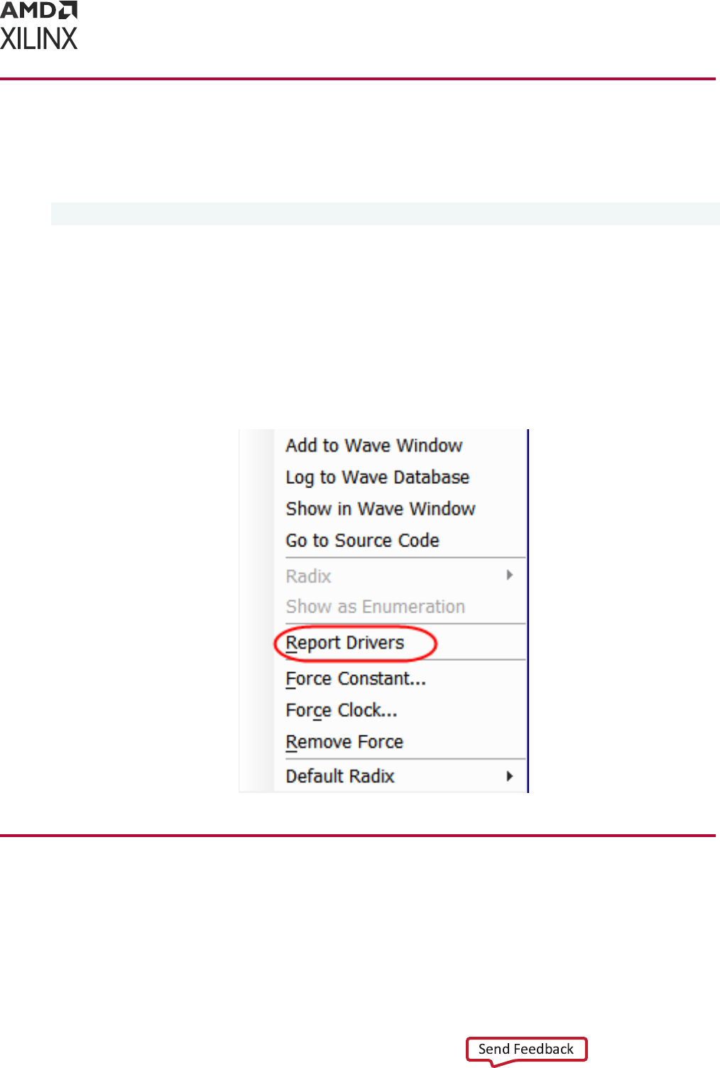
Using the report_drivers Tcl Command
You can use the report_drivers Tcl command to determine what signal is driving a value on
an HDL object. The syntax is as follows:
report_drivers <hdl_object>
The command prints drivers (HDL statements doing the assignment) to the Tcl Console along
with current driving values on the right side of the assignment to a wire or signal-type HDL
object.
You can also call the report_drivers command from the Object or Wave window context
menu or text editor. To open the context menu (shown in the gure below), right-click any signal
and click Report Drivers. The result appears in the Tcl console.
Figure 41: Context Menu with Report Drivers Command Option
Using the Value Change Dump Feature
You can use a Value Change Dump (VCD) le to capture simulaon output. The Tcl commands
are based on Verilog system tasks related to dumping values.
For the VCD feature, the Tcl commands listed in the table below model the Verilog system tasks.
Chapter 6: Debugging a Design with Vivado Simulator
UG900 (v2022.1) April 21, 2022 www.xilinx.com
Vivado Design Suite User Guide: Logic Simulation 127

Table 13: Tcl Commands for VCD
Tcl Command Description
open_vcd
Opens a VCD file for capturing simulation output. This Tcl command models the behavior
of $dumpfile Verilog system task.
checkpoint_vcd
Models the behavior of the $dumpall Verilog system task.
start_vcd
Models the behavior of the $dumpon Verilog system task.
log_vcd
Logs VCD for the specified HDL objects. This command models behavior of the
$dumpvars Verilog system task.
flush_vcd
Models behavior of the $dumpflush Verilog system task.
limit_vcd
Models behavior of the $dumplimit Verilog system task.
stop_vcd
Models behavior of the $dumpoff Verilog system task.
close_vcd
Closes the VCD generation.
See the Vivado Design Suite Tcl Command Reference Guide (UG835), or type the following in the Tcl
Console:
<command> -help
Example:
open_vcd xsim_dump.vcd
log_vcd /tb/dut/*
run all
close_vcd
quit
See Verilog Language Support Excepons for more informaon.
You can use the VCD data to validate the output of the simulator to debug simulaon failures.
Related Information
Vivado Simulator Mixed Language Support and Language Excepons
Using the log_wave Tcl Command
The log_wave command logs simulaon output for viewing specied HDL objects with the
Vivado simulator waveform viewer. Unlike add_wave, the log_wave command does not add
the HDL object to the waveform viewer (that is, the Waveform Conguraon). It simply enables
the logging of output to the Vivado simulator Waveform Database (WDB).
TIP:
To display object values prior to the me of inseron, the simulaon must be restarted. To avoid
having to restart the simulaon because of missing value changes: issue the log_wave -r / Tcl command at
the start of a simulaon run to capture value changes for all display-able HDL objects in your design.
Chapter 6: Debugging a Design with Vivado Simulator
UG900 (v2022.1) April 21, 2022 www.xilinx.com
Vivado Design Suite User Guide: Logic Simulation 128

Syntax:
log_wave [-recursive] [-r] [-quiet] [-verbose] <hdl_objects>...
Example log_wave TCL Command Usage
To log the waveform output for:
• All signals in the design (excluding those of alternate top modules):
log_wave -r /
• All signals in a scope: /tb:
log_wave /tb/*
• Those objects having names that start with a and end in b and have digits in between:
log_wave [get_objects -regexp {^a[0-9]+b$}]
• All objects in the current scope and all child scopes, recursively:
log_wave -r *
• Temporarily overriding any message limits and return all messages from the following
command:
log_wave -v
• The objects in the current scope:
log_wave *
• Only the ports of the scope /tb/UUT, use the command:
log_wave [get_objects -filter {type == in_port || type == out_port ||
type ==
inout_port || type == port} /tb/UUT/*]
• Only the internal signals of the scope /tb/UUT, use the command:
log_wave [get_objects -filter {type == signal} /tb/UUT/*]
The wave conguraon sengs; which include the signal order, name style, radix, and color; are
saved to the wave conguraon (WCFG) le upon demand. See Chapter 5: Analyzing Simulaon
Waveforms with Vivado Simulator.
Chapter 6: Debugging a Design with Vivado Simulator
UG900 (v2022.1) April 21, 2022 www.xilinx.com
Vivado Design Suite User Guide: Logic Simulation 129
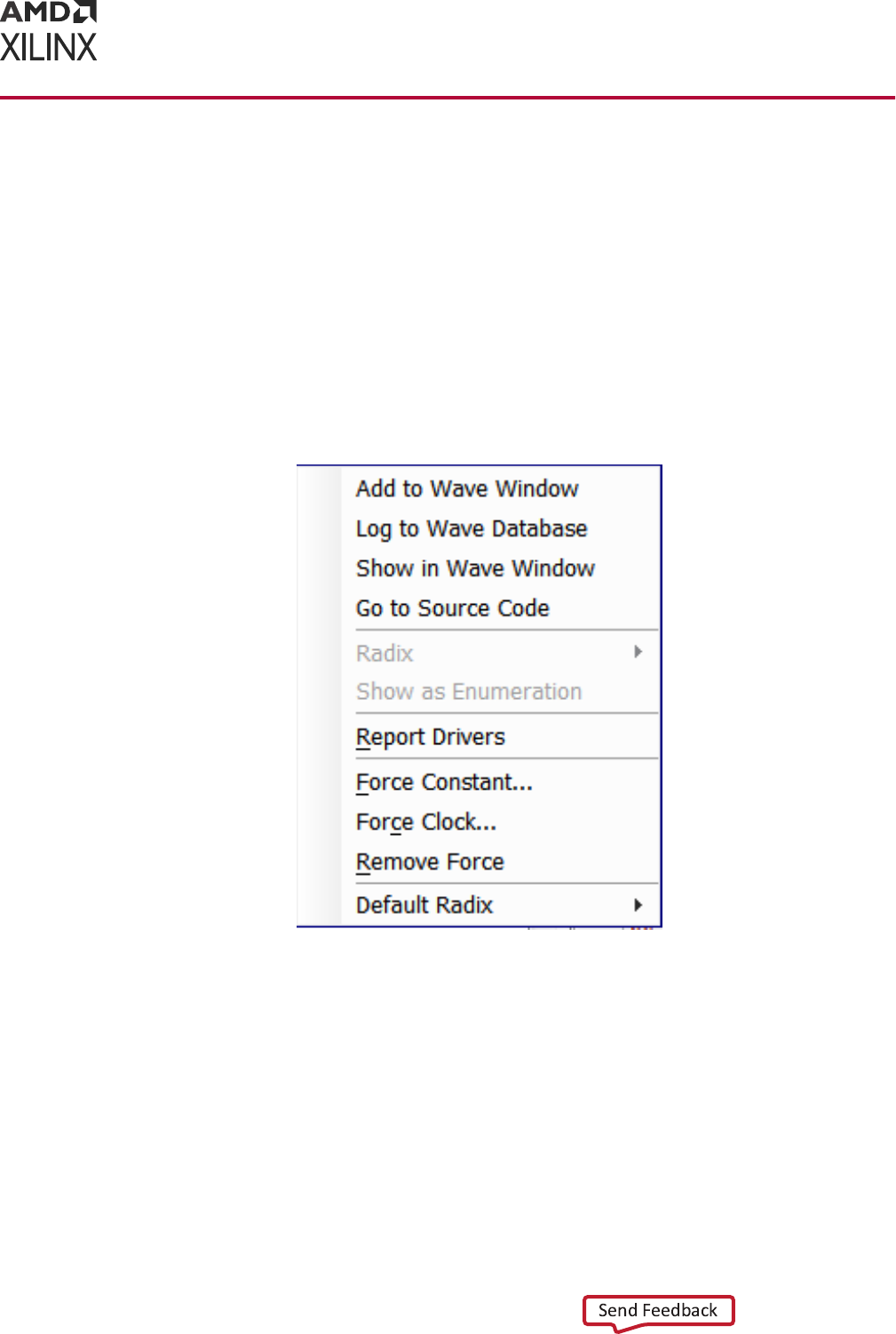
Cross Probing Signals in the Object, Wave,
and Text Editor Windows
In Vivado simulator, you can do cross probing on signals present in the Objects, Wave, and text
editor windows.
From the Objects window, you can check to see if a signal is present in the Wave window and
vice versa. Right-click the signal to open the context menu shown in the following gure. Click
Show in Wave Window or Add to Wave Window (if signal is not yet present in the Wave
window).
Figure 42: Objects Window Context Menu Options
You can also cross probe a signal from the text editor. Right-click a signal to open the context
menu shown in the gure below. Select Add to Wave Window, Show in Waveform or Show in
Objects. The signal then appears highlighted in the Wave or Objects window.
Chapter 6: Debugging a Design with Vivado Simulator
UG900 (v2022.1) April 21, 2022 www.xilinx.com
Vivado Design Suite User Guide: Logic Simulation 130
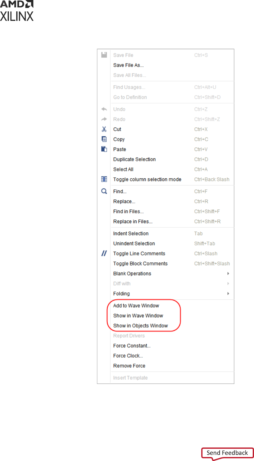

Tool Specific init.tcl
During execuon of simulaon, Vivado simulator sources the init le present at the following
locaon:
$HOME/.xilinx/xsim/xsim_init.tcl
It is useful, if you want to set a property across mulple runs. In such a scenario, you can write
these inside a tcl le and Vivado simulator will source this tcl le before me 0' during execuon.
Subprogram Call-Stack Support
You can now step-through subprogram calls and access automac (as well as stac) variables
inside subprogram using get_value/set_value opons.
Currently, you can only access these variables if the subprogram is at the top of the call-stack.
Use the following opons to support access to variables at any level of the call-stack.
Call Stacks Window
Call Stacks window shows HDL scopes for all the VHDL/Verilog processes in a design which are
waing inside a subprogram at the current simulaon me. This is similar to get_stacks Tcl
command.
By default, the current process in which simulaon is stopped (inside a subprogram) will be
selected in the Call Stacks window. However, you can select any other processes waing in a
subprogram. The eect of selecng a process on the Call Stack window is same as selecng a
process scope from the Scope window or using current_scope Tcl command. When you
select a process on the Call Stacks window, the updated process appears in the Scope window,
Objects window, Stack Frames window and Locals tab. The process name with absolute path and
its type of the selected process is shown in the Call Stacks window.
Chapter 6: Debugging a Design with Vivado Simulator
UG900 (v2022.1) April 21, 2022 www.xilinx.com
Vivado Design Suite User Guide: Logic Simulation 132
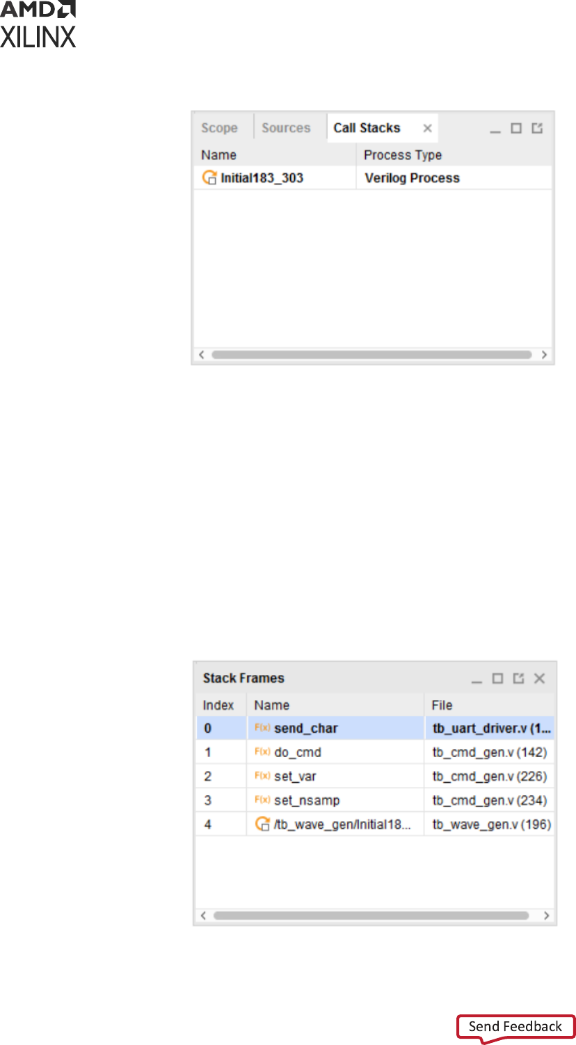
Figure 44: Call Stacks Window
Stack Frames Window
Stack Frames window shows the current HDL process that is waing inside a subprogram and
the subprograms in its call-stack. This is similar to report_frames and current_frame Tcl
commands. In the Stack Frames windows, the most recent subprogram in the current hierarchy is
shown at the top, followed by caller subprograms. The caller HDL process is shown the boom.
You can select other frames to be current and the eect is same as the current_frame –set
<selected_frame_index> Tcl command. The Locals tab in the Objects window follows the
subprogram frame selecon and shows the stac and automac variables local to the selected
subprogram frame. The frame number, subprogram/process name, source le and current line for
the selected HDL process is shown in the Stack Frames window.
Figure 45: Stack Frames Window
Chapter 6: Debugging a Design with Vivado Simulator
UG900 (v2022.1) April 21, 2022 www.xilinx.com
Vivado Design Suite User Guide: Logic Simulation 133
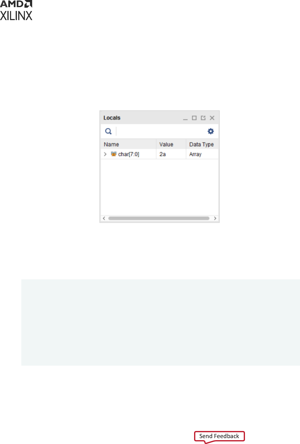
Locals Tab in Objects Window
The Locals tab in Objects window shows the name, value and type of stac and automac
variables local to the currently execung (or selected) subprogram. This is similar to
get_objects –local Tcl command. This window follows the frame selected in the Stack
Frames window. For every variable/argument, its name, value and type would be shown in the
Locals tab.
Figure 46: Locals Tab in Objects Window
Debugging with Dynamic Type
In the SystemVerilog, there are dynamic types such as Class, Dynamic Array, Queue, and
Associave Array etc. These dynamic types are supported in the Vivado simulator. Vivado allows
you to probe the dynamic type variables. For example:
module top();
int dynamicArray[];
byte queue[$];
initial
begin
dynamicArray = new[3];
dynamicArray = '{10, 20, 30};
queue.push_back(8'hab);
queue.push_back(8'hff);
#10;
dynamicArray = new[5](dynamicArray);
$display(queue.pop_front());
end
endmodule
You can probe the dynamic type variables using the following windows as shown in the following
gure:
• Objects window
Chapter 6: Debugging a Design with Vivado Simulator
UG900 (v2022.1) April 21, 2022 www.xilinx.com
Vivado Design Suite User Guide: Logic Simulation 134
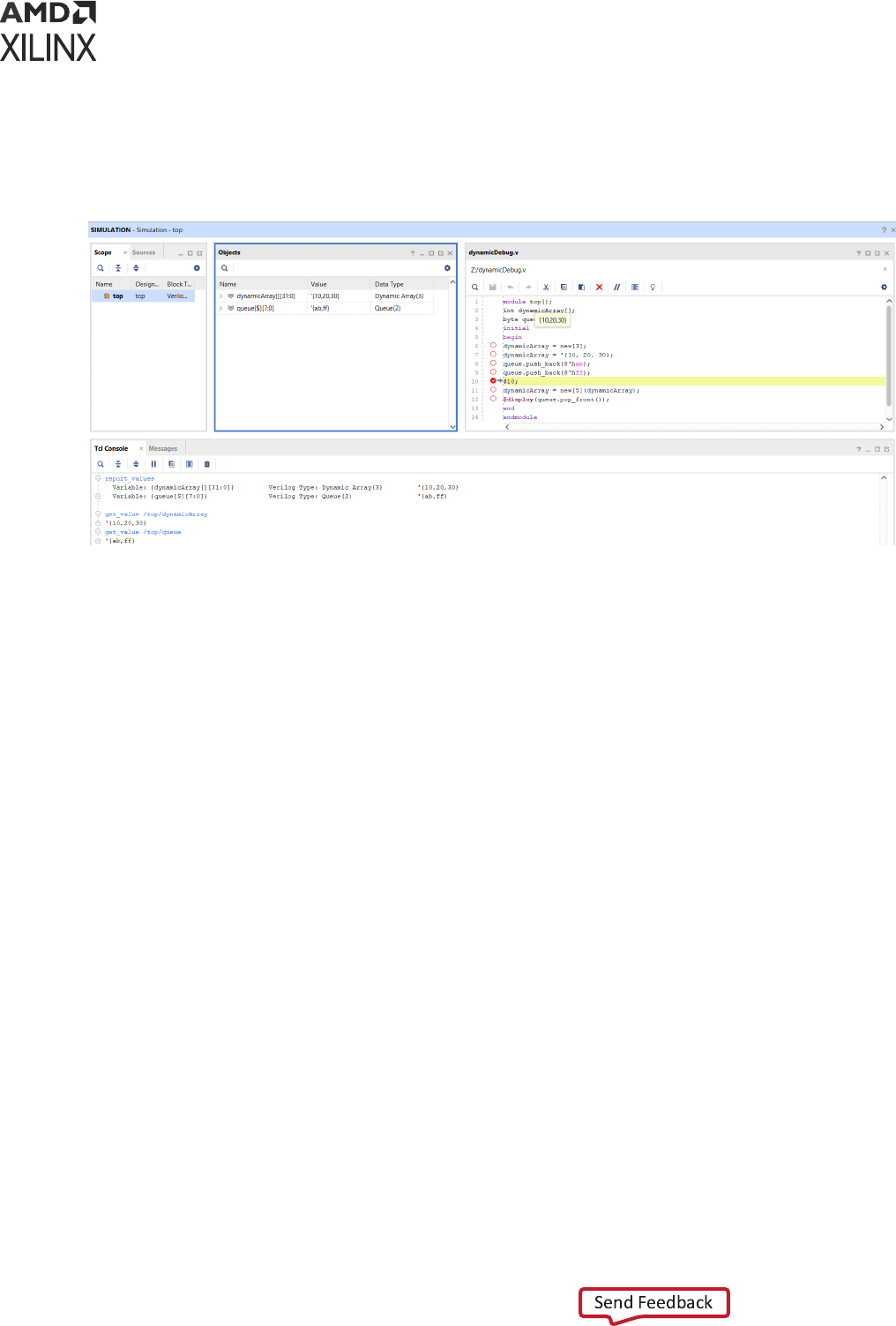
• Tcl Console window by using get_value and report_value commands.
• Toolp in the Sources window
Figure 47: Probing Dynamic Type
Note: Dynamic types are not supported for tracing waveform (add_wave) or for creang waveform
data base (log_wave).
Chapter 6: Debugging a Design with Vivado Simulator
UG900 (v2022.1) April 21, 2022 www.xilinx.com
Vivado Design Suite User Guide: Logic Simulation 135

Chapter 7
Simulating in Batch or Scripted
Mode in Vivado Simulator
This chapter describes the command line compilaon and simulaon process.
Vivado supports an integrated simulaon ow where the tool can launch Vivado simulator, or a
third party simulator from the IDE. However, many users also want to run simulaon in batch or
scripted mode in their vericaon environment, which may include system-level simulaon, or
advanced vericaon such as UVM. The Vivado Design Suite supports batch or scripted
simulaon in the Vivado simulator.
This chapter describes a process to gather the needed design les, to generate simulaon scripts
for your target simulator, and to run simulaon in batch mode. The simulaon scripts can be
generated for a top-level HDL design, or for hierarchical modules, managed IP projects, or block
designs from Vivado IP integrator. Batch simulaon is supported in both project and non-project
script-based ow.
Exporting Simulation Files and Scripts
Running a simulaon from the command line for either a behavioral or ming simulaon requires
you to perform the following steps:
1. Idenfying and parsing design les.
2. Elaborang and generang an executable simulaon snapshot of the design.
3. Running simulaon using the executable snapshot.
The Vivado Design Suite provides an Export Simulaon command to let you quickly gather the
design les required for simulaon, and generate the simulaon scripts for the top-level RTL
design, or a sub-design. The export_simulation command will generate scripts for all of the
supported third-party simulators, or for the target simulator of your choice.
From within the Vivado IDE, use the File → Export → Export Simulaon command to open the
Export Simulaon dialog box as shown in the following gure.
Chapter 7: Simulating in Batch or Scripted Mode in Vivado Simulator
UG900 (v2022.1) April 21, 2022 www.xilinx.com
Vivado Design Suite User Guide: Logic Simulation 136
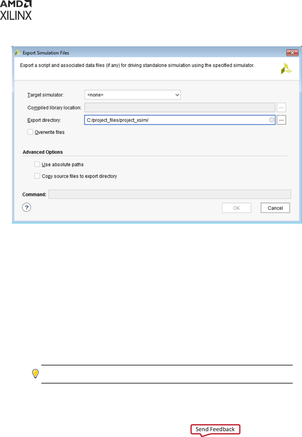
Figure 48: Export Simulation Dialog Box
The Export Simulaon command writes a simulaon script le for all supported simulators, or for
the specied Target simulator. The generated scripts will contain simulator commands for
compiling, elaborang, and simulang the design.
The features of the Export Simulaon dialog box include the following:
• Target simulator: Species all simulators, or a specic simulator to generate command line
scripts for. Target simulators include Vivado simulator as well as various supported third-party
simulators. Refer to Chapter 3: Simulang with Third-Party Simulators for more informaon.
Note: On the Windows operang system, scripts will only be generated for those simulators that run on
Windows.
• Compiled library locaon: In order to perform simulaon with the script generated by Export
Simulaon, your simulaon libraries must rst be compiled with the compile_simlib Tcl
command. The generated scripts will automacally include the setup les needed for the
target simulator from the compiled library directory. Refer to Compiling Simulaon Libraries
for more informaon.
TIP:
It is recommended to provide the path to the Compile library locaon whenever running Export
Simulaon. This insures that the scripts will always point to the correct simulaon libraries.
• Export directory: Species the output directory for the scripts wrien by Export Simulaon.
By default, the simulaon scripts are wrien to the local directory of the current project.
Chapter 7: Simulating in Batch or Scripted Mode in Vivado Simulator
UG900 (v2022.1) April 21, 2022 www.xilinx.com
Vivado Design Suite User Guide: Logic Simulation 137
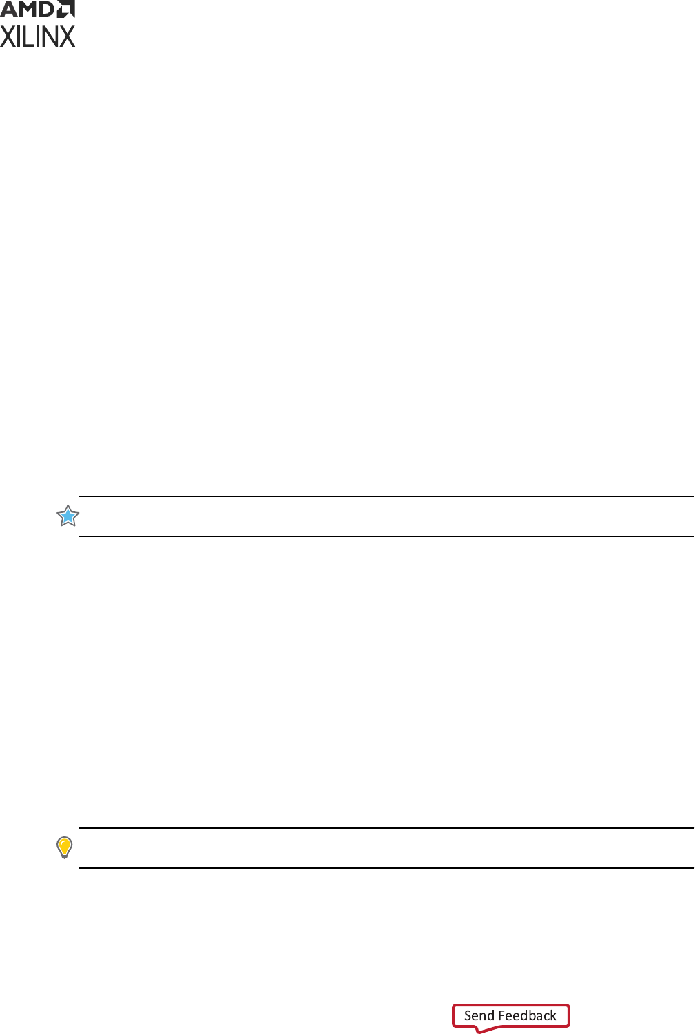
• Overwrite les: Overwrites the les of the same name that already exist in the export
directory.
• Use absolute paths: By default, source les and directory paths in the generated scripts will be
relave to a reference directory that is dened in the scripts. Use this switch to make le
paths in the script absolute rather than relave.
• Copy source les to export directory: Copy design les to the output directory. This copies
the simulaon source les as well as the generated scripts to make the enre simulaon folder
more portable.
• Command: This eld provides the Tcl command syntax for the export_simulation
command that will be run as a result of the various opons and sengs that you have
specied in the Export Simulaon dialog box.
• Help: For detailed informaon on various opons in Export Simulaon les dialog box, click
the help buon.
The Export Simulaon command supports both project and non-project designs. It does not read
properes from the current project to query for Verilog denes and include directories. Instead,
the Export Simulaon command gets direcves from the dialog box or from
export_simulation command opons. You must specify the appropriate opons to get the
results you want. In addion, you must have output products generated for all IP and BD that are
used in the top-level design.
IMPORTANT!
The
export_simulation
command will not generate output products for IP and BD if
they do not exist. Instead it will return an error and exit.
When you click OK on the Export Simulaon dialog box, the command gets the simulaon
compile order of all design les required for simulang the specied design object: the top-level
design, a hierarchical module, IP core, a block design from Vivado IP integrator, or a Managed IP
project with mulple IP. The simulaon compile order of the required design les is exported to a
shell script with compiler commands and opons for the target simulator.
The simulaon scripts are wrien to separate folders in the Export directory as specied in the
Export Simulaon dialog box. A separate folder is created for each specied simulator, and
compile, elaborate, and simulate scripts are wrien for the simulator.
The scripts generated by the Export Simulaon command uses a 3-step process, analyze/
compile, elaborate and simulate, that is common to many simulators including the Vivado
simulator. However, for ModelSim and Riviera the generated scripts use the two-step process of
compile and simulate that the tool requires.
TIP:
To use the two-step process in the Questa simulator, you can start with the scripts generated for
ModelSim and modify them as needed.
Chapter 7: Simulating in Batch or Scripted Mode in Vivado Simulator
UG900 (v2022.1) April 21, 2022 www.xilinx.com
Vivado Design Suite User Guide: Logic Simulation 138

The Export Simulaon command will also copy data les (if any) from the leset, or from an IP, to
the specied export directory. If the design contains Verilog sources, then the generated script
will also copy the glbl.v le from the Vivado soware installaon path to the output directory.
export_ip_user_files -no_script -force
export_simulation -directory "C:/Data/project_wave1" -simulator all
When you run the Export Simulaon command from the dialog box, the Vivado IDE actually runs
a sequence of commands that denes the base directory (or locaon) for the exported scripts,
exports the IP user les, and then runs the export_simulation command.
The export_ip_user_files command is run automacally by the Vivado IDE to ensure that
all required les needed to support simulaon for both core container and non-core container IP,
as well as block designs, are available. See this link in the Vivado Design Suite User Guide: Designing
with IP (UG896) for more informaon. While export_ip_user_files is run automacally
when working with the Export Simulaon dialog box, you must be sure to run it manually before
running the export_simulation command.
TIP: Noce the
-no_script
opon is specied when
export_ip_user_files
is run automacally
by the Vivado IDE. This is to prevent the generaon of simulaon scripts for the individual IP and BDs that
are used in the top-level design because it can add signicant run me to the command. However, you can
generate these simulaon scripts for individual IP and BD by running
export_ip_user_files
on
specied objects (
-of_objects
), or without the
-no_script
opon.
The export_ip_user_files command sets up the user le environment for IP and block
design needed for simulaon and synthesis. The command creates a folder called
ip_user_files which contains instanaon templates, stub les for use with third-party
synthesis tools, wrapper les, memory inializaon les, and simulaon scripts.
The export_ip_user_files command also consolidates stac simulaon les that are
shared across all IP and block designs in the project and copies them to an ipstatic folder.
Many of the IP les that are shared across mulple IP and BDs in a project do not change for
specic IP customizaons. These stac les are copied into the ipstatic directory. The scripts
created for simulaon reference the shared les in this directory as needed. The dynamic
simulaon les that are specic to an IP customizaon are copied to the IP folder. See this link,
or "Understanding IP User Files" in Vivado Design Suite User Guide: Designing with IP (UG896) for
more informaon.
IMPORTANT!
The scripts and les generated by the
export_simulation
command point to the les
in the
ip_user_files
directory. You must run the
export_ip_user_files
command before you
run
export_simulation
or simulaon errors may occur.
Chapter 7: Simulating in Batch or Scripted Mode in Vivado Simulator
UG900 (v2022.1) April 21, 2022 www.xilinx.com
Vivado Design Suite User Guide: Logic Simulation 139

Exporting the Top Level Design
To create simulaon scripts for the top-level RTL design use export_simulation and provide
the simulaon leset object. In the following example sim_1 is the simulaon leset, and export
simulaon will create simulaon scripts for all the RTL enes, IP, and BD objects in the design.
export_ip_user_files -no_script
export_simulation -of_objects [get_filesets sim_1] -directory C:/test_sim \
-simulator questa
Exporting IP from the Xilinx Catalog and Block
Designs
To generate scripts for an IP, or a Vivado IP integrator block design, you can simply run the
command on the IP or block design object:
export_ip_user_files -of_objects [get_ips blk_mem_gen_0] -no_script -force
export_simulation -simulator xcelium -directory ./export_script \
-of_objects [get_ips blk_mem_gen_0]
Or, export the ip_user_les for all IP and BDs in the design:
export_ip_user_files -no_script -force
export_simulation -simulator xcelium -directory ./export_script
You can also generate simulaon scripts for block design objects:
export_ip_user_files -of_objects [get_files base_microblaze_design.bd] \
-no_script -force
export_simulation -of_objects [get_files base_microblaze_design.bd] \
-directory ./sim_scripts
IMPORTANT!
You must have output products generated for all IP and BD that are used in the top-level
design. The
export_simulation
command will not generate output products for IP and BD if they do
not exist. Instead it will return an error and exit.
Exporting a Manage IP Project
Manage IP project provides users an ability to create and manage a centralized repository of
customized IPs. See this link in the Vivado Design Suite User Guide: Designing with IP (UG896) for
more informaon on Manage IP projects. When generang the IP output products for Manage IP
projects, the Vivado tool also generates simulaon scripts for each IP using the
export_ip_user_files command as previously discussed.
Chapter 7: Simulating in Batch or Scripted Mode in Vivado Simulator
UG900 (v2022.1) April 21, 2022 www.xilinx.com
Vivado Design Suite User Guide: Logic Simulation 140
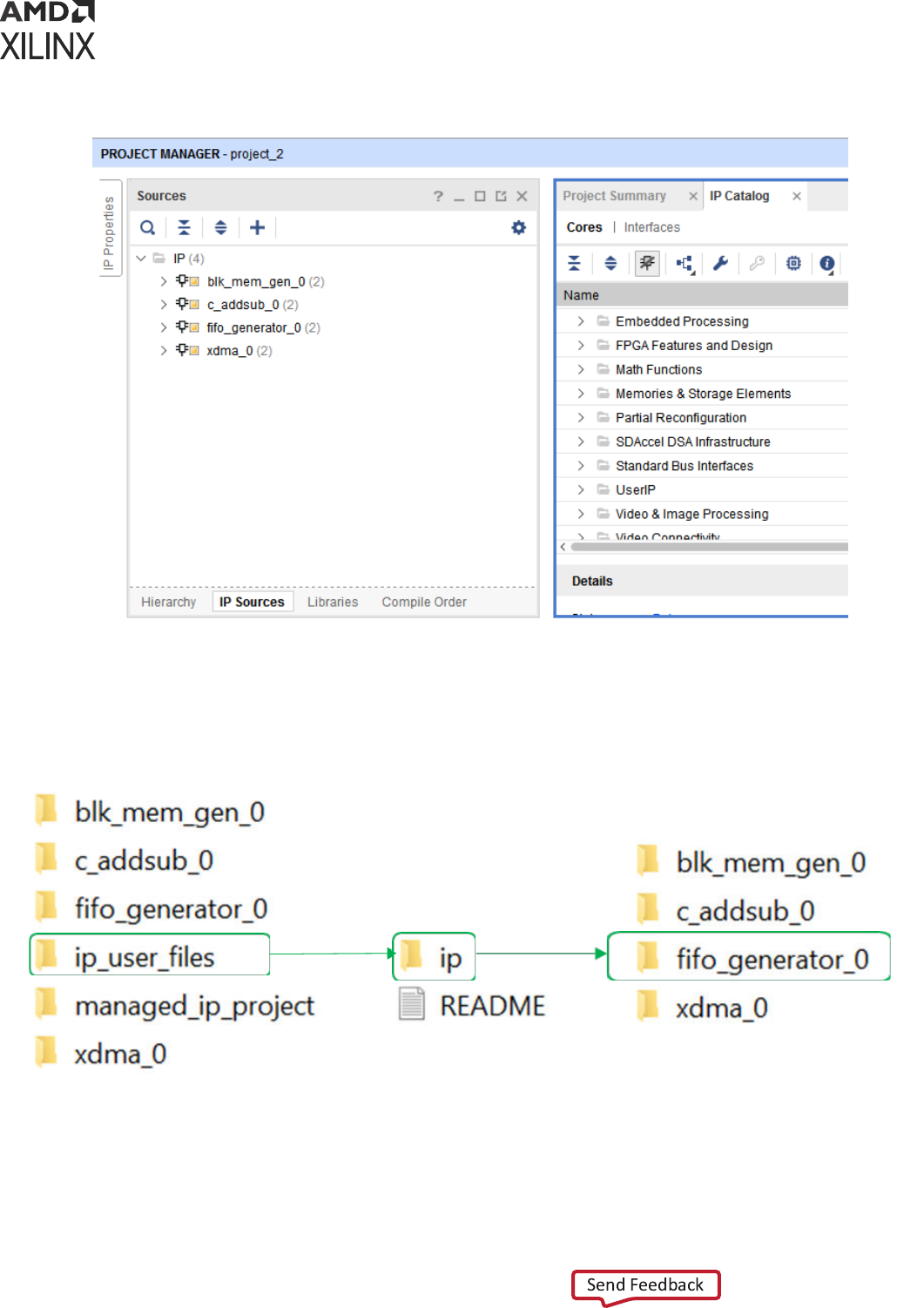
Figure 49: Managed IP Project
The Managed IP Project shown above features four dierent customized IP: blk_mem_gen_0,
c_addsub_0, fifo_generator_0, xdma_0. For this project the Vivado Design Suite creates
an ip_user_files folder as shown in the following gure.
Figure 50: Managed IP Directory Structure
Chapter 7: Simulating in Batch or Scripted Mode in Vivado Simulator
UG900 (v2022.1) April 21, 2022 www.xilinx.com
Vivado Design Suite User Guide: Logic Simulation 141
The ip_user_files folder is generated by the export_ip_user_files command as
previously described. When this command is run on a Manage IP project, it will recursively
process all the IP in the project and generate the scripts and other les needed for synthesis and
simulaon of the IP. The ip_user_files folder contains the scripts used for batch simulaon,
as well as the dynamic and stac IP les needed to support simulaon.
The simulaon scripts for your target simulator, or for all supported simulators, are located in
the ./sim_scripts folder as seen in Exporng a Manage IP Project. You can go to the folder
of your target simulator and incorporate the compile, elaborate, and simulate scripts into
your simulaon ow.
The Vivado tool consolidates all the shared simulaon les, used by mulple IP and BD in the
design, into a folder called ./ipstatic. The dynamic les that vary depending on the specics
of an IP customizaon are located in the ./ip folder.
TIP: In addion to exporng all the IP in a Manage IP project, you can use the steps outlined in Exporng
IP from the Xilinx Catalog and Block Designs to generate scripts for individual IP in the project.
Running the Vivado Simulator in Batch Mode
To run in batch or scripted mode, the Vivado simulator relies on three processes which are
supported by the les generated by the export_simulation command.
• Parsing Design Files, xvhdl and xvlog
• Elaborang and Generang a Design Snapshot, xelab
• Simulang the Design Snapshot, xsim
For ming simulaon, there are addional steps and data required to complete the simulaon, as
described in the following:
• Generang a Timing Netlist
• Running Post-Synthesis and Post-Implementaon Simulaons
Parsing Design Files, xvhdl and xvlog
The xvhdl and xvlog commands parse VHDL and Verilog les, respecvely. Descripons for
each opon are available in Table 15: xelab, xvhd, and xvlog Command Opons.
xvhdl
The xvhdl command is the VHDL analyzer (parser).
Chapter 7: Simulating in Batch or Scripted Mode in Vivado Simulator
UG900 (v2022.1) April 21, 2022 www.xilinx.com
Vivado Design Suite User Guide: Logic Simulation 142

xvhdl Syntax
xvhdl
[-encryptdumps]
[-f [-file] <filename>]
[-h [-help]
[-initfile <init_filename>]
[-L [-lib] <library_name> [=<library_dir>]]
[-log <filename>]
[-nolog]
[-prj <filename>]
[-relax]
[-v [verbose] [0|1|2]]
[-version]
[-work <library_name> [=<library_dir>]
[-incr]
[-2008]
[-93_mode]
[-nosignalhandlers]
This command parses the VHDL source le(s) and stores the parsed dump into a HDL library on
disk.
xvhdl Examples
xvhdl file1.vhd file2.vhd
xvhdl -work worklib file1.vhd file2.vhd
xvhdl -prj files.prj
xvlog
The xvlog command is the Verilog parser. The xvlog command parses the Verilog source le(s)
and stores the parsed dump into a HDL library on disk.
xvlog Syntax
xvlog
[-d [define] <name>[=<val>]]
[-encryptdumps]
[-f [-file] <filename>]
[-h [-help]]
[-i [include] <directory_name>]
[-initfile <init_filename>]
[-L [-lib] <library_name> [=<library_dir>]]
[-log <filename>]
[-nolog]
[-noname_unamed_generate]
[-relax]
[-prj <filename>]
[-sourcelibdir <sourcelib_dirname>]
[-sourcelibext <file_extension>]
[-sourcelibfile <filename>]
[-sv]
[-v [verbose] [0|1|2]]
Chapter 7: Simulating in Batch or Scripted Mode in Vivado Simulator
UG900 (v2022.1) April 21, 2022 www.xilinx.com
Vivado Design Suite User Guide: Logic Simulation 143

[-version]
[-work <library_name> [=<library_dir>]
[-incr]
[-nosignalhandlers]
[-uvm_version arg]
xvlog Examples
xvlog file1.v file2.v
xvlog -work worklib file1.v file2.v
xvlog -prj files.prj
Note: xelab, xvlog and xvhdl are not Tcl commands. The xvlog, xvhdl, xelab are Vivado-
independent compiler executables. Hence, there is no Tcl command for them.
The simulaon launching is Vivado dependent and hence is done through xsim Tcl command.
For usage of simulaon outside Vivado, an executable by the same name as xsim is provided.
The xsim executable launches Vivado in project less mode and executes xsim Tcl command to
launch simulaon. Hence, to get help on xvlog, xvhdl, xelab form within Vivado IDE, please
precede the command with exec.
Example: exec xvlog –help.
To get help on xsim, use xsim –help.
Elaborating and Generating a Design
Snapshot, xelab
Simulaon with the Vivado simulator happens in two phases:
• In the rst phase, the simulator compiler xelab, compiles your HDL model into a snapshot,
which is a representaon of the model in a form that the simulator can execute.
• In the second phase, the simulator loads and executes (using the xsim command) the
snapshot to simulate the model. In Non-Project Mode, you can reuse the snapshot by skipping
the rst phase and repeang the second.
When the simulator creates a snapshot, it assigns the snapshot a name based on the names of
the top modules in the model. You can, however, override the default by specifying a snapshot
name as an opon to the compiler. Snapshot names must be unique in a directory or SIMSET;
reusing a snapshot name, whether default or custom, results in overwring a previously-built
snapshot with that name.
IMPORTANT!
You cannot run two simulaons with the same snapshot name in the same directory or
SIMSET.
Chapter 7: Simulating in Batch or Scripted Mode in Vivado Simulator
UG900 (v2022.1) April 21, 2022 www.xilinx.com
Vivado Design Suite User Guide: Logic Simulation 144
xelab
The xelab command, for given top-level units, does the following:
• Loads children design units using language binding rules or the -L <library> command line
specied HDL libraries
• Performs a stac elaboraon of the design (sets parameters, generics, puts generate
statements into eect, and so forth)
• Generates executable code
• Links the generated executable code with the simulaon kernel library to create an executable
simulaon snapshot
You then use the produced executable simulaon snapshot name as an opon to the xsim
command along with other opons to eect HDL simulaon.
TIP:
xelab
can implicitly call the parsing commands,
xvlog
and
xvhdl
. You can incorporate the
parsing step by using the
xelab -prj
opon. See Project File (.prj) Syntax for more informaon about
project les.
Note: xelab, xvlog and xvhdl are not Tcl commands. The xvlog, xvhdl, xelab are Vivado-
independent compiler executables. Hence, there is no Tcl command for them.
xelab Command Syntax Options
Descripons for each opon are available in the following codeblock.
xelab
[-d [define] <name>[=<val>]
[-debug <kind>]
[-f [-file] <filename>]
[-generic_top <value>]
[-h [-help]
[-i [include] <directory_name>]
[-initfile <init_filename>]
[-log <filename>]
[-L [-lib] <library_name> [=<library_dir>]
[-maxdesigndepth arg]
[-mindelay]
[-typdelay]
[-maxarraysize arg]
[-maxdelay]
[-mt arg]
[-nolog]
[-noname_unnamed_generate]
[-notimingchecks]
[-nosdfinterconnectdelays]
[-nospecify]
[-O arg]
[-override_timeunit]
[-override_timeprecision]
[-prj <filename>]
[-pulse_e arg]
[-pulse_r arg]
[-pulse_int_e arg]
Chapter 7: Simulating in Batch or Scripted Mode in Vivado Simulator
UG900 (v2022.1) April 21, 2022 www.xilinx.com
Vivado Design Suite User Guide: Logic Simulation 145

[-pulse_int_r arg]
[-pulse_e_style arg]
[-r [-run]]
[-R [-runall]]
[-rangecheck]
[-relax]
[-s [-snapshot] arg]
[-sdfnowarn]
[-sdfnoerror]
[-sdfroot <root_path>]
[-sdfmin arg]
[-sdftyp arg]
[-sdfmax arg]
[-sourcelibdir <sourcelib_dirname>]
[-sourcelibext <file_extension>]
[-sourcelibfile <filename>]
[-stats]
[-timescale]
[-timeprecision_vhdl arg]
[-transport_int_delays]
[-v [verbose] [0|1|2]]
[-version]
[-sv_root arg]
[-sv_lib arg]
[-sv_liblist arg]
[-dpiheader arg]
[-driver_display_limit arg]
[-dpi_absolute]
[-incr]
[-93_mode]
[-nosignalhandlers]
[-dpi_stacksize arg]
[-transform_timing_checkers]
[-a[ --standalone]
[-ignore_assertions]
[-ignore_coverage]
[-cov_db_dir arg]
[-cov_db_name arg]
[-uvm_version arg]
[-report_assertion_pass]
[-dup_entity_as_module]
[-cc_celldefines]
[-cc_libs]
[-cc_type arg]
[-cc_db arg]
[-cc_dir arg]
[-cov_db_dir arg]
[-cov_db_name arg]
[-ignore_localparam_override]
[-sc_lib arg]
[-sc_root arg]
xelab Examples
xelab work.top1 work.top2 -s cpusim
xelab lib1.top1 lib2.top2 -s fftsim
xelab work.top1 work.top2 -prj files.prj -s pciesim
xelab lib1.top1 lib2.top2 -prj files.prj -s ethernetsim
Chapter 7: Simulating in Batch or Scripted Mode in Vivado Simulator
UG900 (v2022.1) April 21, 2022 www.xilinx.com
Vivado Design Suite User Guide: Logic Simulation 146

Verilog Search Order
The xelab command uses the following search order to search and bind instanated Verilog
design units:
1. A library specied by the 'uselib direcve in the Verilog code. For example:
module
full_adder(c_in, c_out, a, b, sum)
input c_in,a,b;
output c_out,sum;
wire carry1,carry2,sum1;
`uselib lib = adder_lib
half_adder adder1(.a(a),.b(b),.c(carry1),.s(sum1));
half_adder adder1(.a(sum1),.b(c_in),.c(carry2),.s(sum));
c_out = carry1 | carry2;
endmodule
2. Libraries specied on the command line with -lib|-L switch.
3. A library of the parent design unit.
4. The work library.
Verilog Instantiation Unit
When a Verilog design instanates a component, the xelab command treats the component
name as a Verilog unit and searches for a Verilog module in the user-specied list of unied
logical libraries in the user-specied order.
• If found, xelab binds the unit and the search stops.
• If the case-sensive search is not successful, xelab performs a case-insensive search for a
VHDL design unit name constructed as an extended idener in the user-specied list and
order of unied logical libraries, selects the rst one matching name, then stops the search.
• If xelab nds a unique binding for any one library, it selects that name and stops the search.
Note: For a mixed language design, the port names used in a named associaon to a VHDL enty
instanated by a Verilog module are always treated as case insensive. Also note that you cannot use a
defparam statement to modify a VHDL generic. See Using Mixed Language Simulaon, for more
informaon.
IMPORTANT! Connecng a whole VHDL record object to a Verilog object is unsupported.
VHDL Instantiation Unit
When a VHDL design instanates a component, the xelab command treats the component
name as a VHDL unit and searches for it in the logical work library.
• If a VHDL unit is found, the xelab command binds it and the search stops.
Chapter 7: Simulating in Batch or Scripted Mode in Vivado Simulator
UG900 (v2022.1) April 21, 2022 www.xilinx.com
Vivado Design Suite User Guide: Logic Simulation 147

• If xelab does not nd a VHDL unit, it treats the case-preserved component name as a Verilog
module name and connues a case-sensive search in the user-specied list and order of
unied logical libraries. The command selects the rst matching the name, then stops the
search.
• If case sensive search is not successful, xelab performs a case-insensive search for a
Verilog module in the user-specied list and order of unied logical libraries. If a unique
binding is found for any one library, the search stops.
`uselib Verilog Directive
The Verilog `uselib direcve is supported, and sets the library search order.
`uselib Syntax
<uselib compiler directive> ::= `uselib [<Verilog-XL uselib directives>|
<lib
directive>]
<Verilog-XL uselib directives> :== dir = <library_directory> | file =
<library_file>
| libext = <file_extension>
<lib directive>::= <library reference> {<library reference>}
<library reference> ::= lib = <logical library name>
`uselib Lib Semantics
The `uselib lib direcve cannot be used with any of the Verilog-XL `uselib direcves. For
example, the following code is illegal:
`uselib dir=./ file=f.v lib=newlib
Mulple libraries can be specied in one `uselib direcve.
The order in which libraries are specied determines the search order. For example:
`uselib lib=mylib lib=yourlib
Species that the search for an instanated module is made in mylib rst, followed by
yourlib.
Like the direcves, such as `uselib dir, `uselib file, and `uselib libext, the
`uselib lib direcve is persistent across HDL les in a given invocaon of parsing and
analyzing, just like an invocaon of parsing is persistent. Unless another `uselib direcve is
encountered, a `uselib (including any Verilog XL `uselib) direcve in the HDL source
remains in eect. A `uselib without any argument removes the eect of any currently acve
`uselib <lib|file|dir|libext>.
The following module search mechanism is used for resolving an instanated module or UDP by
the Veric Verilog elaboraon algorithm:
Chapter 7: Simulating in Batch or Scripted Mode in Vivado Simulator
UG900 (v2022.1) April 21, 2022 www.xilinx.com
Vivado Design Suite User Guide: Logic Simulation 148
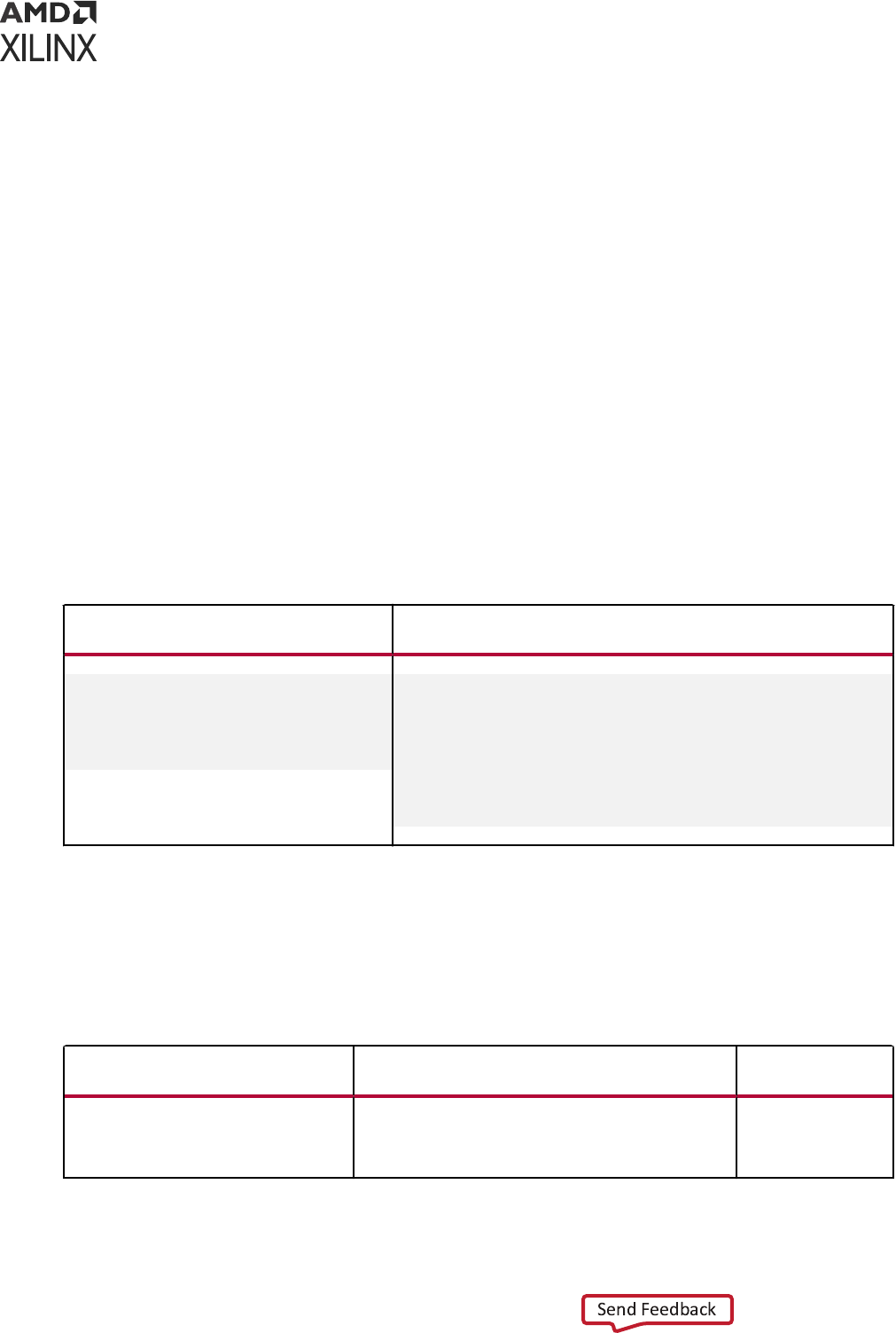
• First, search for the instanated module in the ordered list of logical libraries of the currently
acve `uselib lib (if any).
• If not found, search for the instanated module in the ordered list of libraries provided as
search libraries in xelab command line.
• If not found, search for the instanated module in the library of the parent module. For
example, if module A in library work instanated module B of library mylib and B
instanated module C, then search for module C in the /mylib, library, which is the library of
B (parent of C).
• If not found, search for the instanated module in the work library, which is one of the
following:
○ The library into which HDL source is being compiled
○ The library explicitly set as work library
○ The default work library is named as work
`uselib Examples
Table 14: `uselib Examples
File half_adder.v compiled into
Logical Library Named adder_lib
File full_adder.v compiled into Logical Library Named
Work
module half_adder(a,b,c,s);
input a,b;
output c,s;
s = a ^ b;
c = a & b;
endmodule
module
full_adder(c_in, c_out, a, b, sum)
input c_in,a,b;
output c_out,sum;
wire carry1,carry2,sum1;
`uselib lib = adder_lib
half_adder
adder1(.a(a),.b(b),. c(carry1),.s(sum1)); half_adder
adder1(.a(sum1),.b(c_in),.c (carry2),.s(sum)); c_out =
carry1 | carry2; endmodule
xelab, xvhdl, and xvlog xsim Command Options
The following table lists the command opons for the xelab, xvhdl, and xvlog xsim
commands.
Table 15: xelab, xvhd, and xvlog Command Options
Command Option Description
Used by
Command
-d [define] <name>[=<val>]
Define Verilog macros. Use -d|--define for each
Verilog macro. The format of the macro is
<name>[=<val>] where <name> is name of the macro
and <value> is an optional value of the macro.
xelab
Parsing Design Files,
xvhdl and xvlog
Chapter 7: Simulating in Batch or Scripted Mode in Vivado Simulator
UG900 (v2022.1) April 21, 2022 www.xilinx.com
Vivado Design Suite User Guide: Logic Simulation 149

Table 15: xelab, xvhd, and xvlog Command Options (cont'd)
Command Option Description
Used by
Command
-debug <kind>
Compile with specified debugging ability turned on.
The <kind> options are:
• typical: Most commonly used abilities, including:
line and wave.
• line: HDL breakpoint.
• wave: Waveform generation, conditional execution,
force value.
• xlibs: Visibility into Xilinx
®
precompiled libraries.
This option is only available on the command line.
• off: Turn off all debugging abilities (Default).
• all: Uses all the debug options.
xelab
-encryptdumps
Encrypt parsed dump of design units being compiled. Parsing Design Files,
xvhdl and xvlog
Parsing Design Files,
xvhdl and xvlog
-f [-file] <filename>
Read additional options from the specified file. xelab
xsim Executable
Options
Parsing Design Files,
xvhdl and xvlog
Parsing Design Files,
xvhdl and xvlog
-generic_top <value>
Override generic or parameter of a top-level design
unit with specified value. Example: -generic_top
"P1=10"
xelab
-h [-help]
Print this help message. xelab
xsim Executable
Options
Parsing Design Files,
xvhdl and xvlog
Parsing Design Files,
xvhdl and xvlog
-i [include] <directory_name>
Specify directories to be searched for files included
using Verilog `include. Use -i|--include for each
specified search directory.
xelab
Parsing Design Files,
xvhdl and xvlog
-initfile <init_filename>
User-defined simulator initialization file to add to or
override settings provided by the default xsim.ini
file.
xelab
Parsing Design Files,
xvhdl and xvlog
Parsing Design Files,
xvhdl and xvlog
-L [-lib] <library_name>
[=<library_dir>]
Specify search libraries for the instantiated non-VHDL
design units; for example, a Verilog design unit.
Use -L|--lib for each search library. The format of
the argument is <name>[=<dir>] where <name> is the
logical name of the library and <library_dir> is an
optional physical directory of the library.
xelab
Parsing Design Files,
xvhdl and xvlog
Parsing Design Files,
xvhdl and xvlog
Chapter 7: Simulating in Batch or Scripted Mode in Vivado Simulator
UG900 (v2022.1) April 21, 2022 www.xilinx.com
Vivado Design Suite User Guide: Logic Simulation 150

Table 15: xelab, xvhd, and xvlog Command Options (cont'd)
Command Option Description
Used by
Command
-log <filename>
Specify the log file name. Default: <xvlog|xvhdl|
xelab|xsim>.log.
xelab
xsim Executable
Options
Parsing Design Files,
xvhdl and xvlog
Parsing Design Files,
xvhdl and xvlog
-maxarraysize <arg>
Set maximum vhdl array size to be 2**n (Default: n =
28, which is 2**28).
xelab
-maxdelay
Compile Verilog design units with maximum delays. xelab
-maxdesigndepth <arg>
Override maximum design hierarchy depth allowed by
the elaborator (Default: 5000).
xelab
-maxlogsize <arg>
Set the maximum size a log file can reach in MB. The
default setting is unlimited.
xsim Executable
Options
-mindelay
Compile Verilog design units with minimum delays. xelab
-mt <arg>
Specifies the number of sub-compilation jobs which
can be run in parallel. Possible values are auto, off, or
an integer greater than 1.
If auto is specified, xelab selects the number of
parallel jobs based on the number of CPUs on the host
machine. (Default = auto.)
Advanced usage: to further control the -mt option, you
can set the Tcl property as follows:
set_property XELAB.MT_LEVEL off|N
[get_filesets sim_1]
xelab
-nolog
Suppress log file generation. xelab
xsim Executable
Syntax
Parsing Design Files,
xvhdl and xvlog
Parsing Design Files,
xvhdl and xvlog
-noieeewarnings
Disable warnings from VHDL IEEE functions. xelab
-noname_unnamed_generate
Do not generate name for an unnamed generate block. xelab
Parsing Design Files,
xvhdl and xvlog
-notimingchecks
Ignore timing check constructs in Verilog specify
block(s).
xelab
-nosdfinterconnectdelays
Ignore SDF port and interconnect delay constructs in
SDF.
xelab
-nospecify
Ignore Verilog path delays and timing checks. xelab
Chapter 7: Simulating in Batch or Scripted Mode in Vivado Simulator
UG900 (v2022.1) April 21, 2022 www.xilinx.com
Vivado Design Suite User Guide: Logic Simulation 151

Table 15: xelab, xvhd, and xvlog Command Options (cont'd)
Command Option Description
Used by
Command
-O <arg>
Enable or disable optimizations.
• -O 0 = Disable optimizations
• -O 1 = Enable basic optimizations
• -O 2 = Enable most commonly desired
optimizations (Default)
• -O 3 = Enable advanced optimizations
Note: A lower value speeds compilation at expense of
slower simulation: a higher value slows compilation but
simulation runs faster.
xelab
-override_timeunit
Override timeunit for all Verilog modules, with the
specified time unit in -timescale option.
xelab
-override_timeprecision
Override time precision for all Verilog modules, with
the specified time precision in -timescale option.
xelab
-pulse_e <arg>
Path pulse error limit as percentage of path delay.
Allowed values are 0 to 100 (Default is 100).
xelab
-pulse_r <arg>
Path pulse reject limit as percentage of path delay.
Allowed values are 0 to 100 (Default is 100).
xelab
-pulse_int_e arg
Interconnect pulse reject limit as percentage of delay.
Allowed values are 0 to 100 (Default is 100).
xelab
-pulse_int_r <arg>
Interconnect pulse reject limit as percentage of delay.
Allowed values are 0 to 100 (Default is 100).
xelab
-pulse_e_style <arg>
Specify when error about pulse being shorter than
module path delay should be handled. Choices are:
• ondetect: Report error right when violation is
detected.
• onevent: Report error after the module path delay.
Default: onevent
xelab
-prj <filename>
Specify the Vivado simulator project file containing one
or more entries of vhdl|verilog <work lib> <HDL
file name>.
xelab
Parsing Design Files,
xvhdl and xvlog
Parsing Design Files,
xvhdl and xvlog
-r [-run]
Run the generated executable snapshot in command-
line interactive mode.
xelab
-rangecheck
Enable run time value range check for VHDL. xelab
-R [-runall]
Run the generated executable snapshot until the end
of simulation.
xelab
xsim Executable
Syntax
-relax
Relax strict language rules. xelab
Parsing Design Files,
xvhdl and xvlog
Parsing Design Files,
xvhdl and xvlog
Chapter 7: Simulating in Batch or Scripted Mode in Vivado Simulator
UG900 (v2022.1) April 21, 2022 www.xilinx.com
Vivado Design Suite User Guide: Logic Simulation 152

Table 15: xelab, xvhd, and xvlog Command Options (cont'd)
Command Option Description
Used by
Command
-s [-snapshot] <arg>
Specify the name of output simulation snapshot.
Default is <worklib>.<unit>; for example:
work.top. Additional unit names are concatenated
using #; for example: work.t1#work.t2.
xelab
-sdfnowarn
Do not emit SDF warnings. xelab
-sdfnoerror
Treat errors found in SDF file as warning. xelab
-sdfmin <arg>
<root>=<file> SDF annotate <file> at <root> with
minimum delay.
xelab
-sdftyp <arg>
<root>=<file> SDF annotate <file> at <root> with
typical delay.
xelab
-sdfmax <arg>
<root>=<file> SDF annotate <file> at <root> with
maximum delay.
xelab
-sdfroot <root_path>
Default design hierarchy at which SDF annotation is
applied.
xelab
-sourcelibdir
<sourcelib_dirname>
Directory for Verilog source files of uncompiled
modules.
Use -sourcelibdir <sourcelib_dirname> for each
source directory.
xelab
Parsing Design Files,
xvhdl and xvlog
-sourcelibext <file_extension>
File extension for Verilog source files of uncompiled
modules.
Use -sourcelibext <file extension> for source
file extension.
xelab
Parsing Design Files,
xvhdl and xvlog
-sourcelibfile <filename>
File name of a Verilog source file with uncompiled
modules.
xelab
Parsing Design Files,
xvhdl and xvlog
-stat
Print tool CPU and memory usages, and design
statistics.
xelab
-sv
Compile input files in SystemVerilog mode. Parsing Design Files,
xvhdl and xvlog
-timescale
Specify default timescale for Verilog modules. Default:
1ns/1ps.
xelab
-timeprecision_vhdl <arg>
Specify time precision for vhdl designs. Default: 1ps. xelab
-transport_int_delays
Use transport model for interconnect delays. xelab
-typdelay
Compile Verilog design units with typical delays
(Default).
xelab
-v [verbose] [0|1|2]
Specify verbosity level for printing messages. Default =
0.
xelab
Parsing Design Files,
xvhdl and xvlog
Parsing Design Files,
xvhdl and xvlog
-version
Print the compiler version to screen. xelab
xsim Executable
Options
Parsing Design Files,
xvhdl and xvlog
Parsing Design Files,
xvhdl and xvlog
Chapter 7: Simulating in Batch or Scripted Mode in Vivado Simulator
UG900 (v2022.1) April 21, 2022 www.xilinx.com
Vivado Design Suite User Guide: Logic Simulation 153

Table 15: xelab, xvhd, and xvlog Command Options (cont'd)
Command Option Description
Used by
Command
-work <library_name>
[=<library_dir>]
Specify the work library. The format of the argument is
<name>[=<dir>] where:
• <name> is the logical name of the library.
• <library_dir> is an optional physical directory of
the library.
Parsing Design Files,
xvhdl and xvlog
Parsing Design Files,
xvhdl and xvlog
-sv_root <arg>
Root directory of which DPI libraries are to be found.
Default: <current_directory/xsim.dir/xsc>
xelab
--sc_lib arg
Shared library name for SystemC functions; (.dll/.so)
without the file extension
xelab
--sc_root <arg>
Root directory of which SystemC libraries are to be
found. Default: <current_directory>/xsim.dir/
work/xsc
xelab
-sv_lib <arg>
Shared library name for DPI imported functions
(.dll/.so) without the file extension.
xelab
-sv_liblist <arg>
Bootstrap file pointing to DPI shared libraries. xelab
-dpiheader <arg>
Header filename for the exported and imported
functions.
xelab
-driver_display_limit <arg>
Enable driver debugging for signals with maximum size
(Default: n = 65536).
xelab
-dpi_absolute
Use absolute paths instead of LD_LIBRARY_PATH on
Linux for DPI libraries that are formatted as
lib<libname>.so.
xelab
-incr
Enable incremental analysis/elaboration in simulation. Parsing Design Files,
xvhdl and xvlog
Parsing Design Files,
xvhdl and xvlog
xelab
-93_mode
Compile VHDL in pure 93 mode. Parsing Design Files,
xvhdl and xvlog
xelab
-2008
Compile VHDL file in 2008 mode. Parsing Design Files,
xvhdl and xvlog
-nosignalhandlers
Don't allow compiler to trap Antivirus, firewall signal. Parsing Design Files,
xvhdl and xvlog
Parsing Design Files,
xvhdl and xvlog
xelab
-dpi_stacksize <arg>
User defined stack size for DPI task. xelab
-transform_timing_checkers
Transform timing checker to Verilog process. xelab
-a
Generate a standalone non-interactive simulation
executable that performs run-all.
Always use with -R.
To run the simulation faster without any debug
capability, use -standalone with -R. It will invoke the
Simulation standalone without invoking Vivado IDE.
This option will save the license loading time.
xelab
Chapter 7: Simulating in Batch or Scripted Mode in Vivado Simulator
UG900 (v2022.1) April 21, 2022 www.xilinx.com
Vivado Design Suite User Guide: Logic Simulation 154
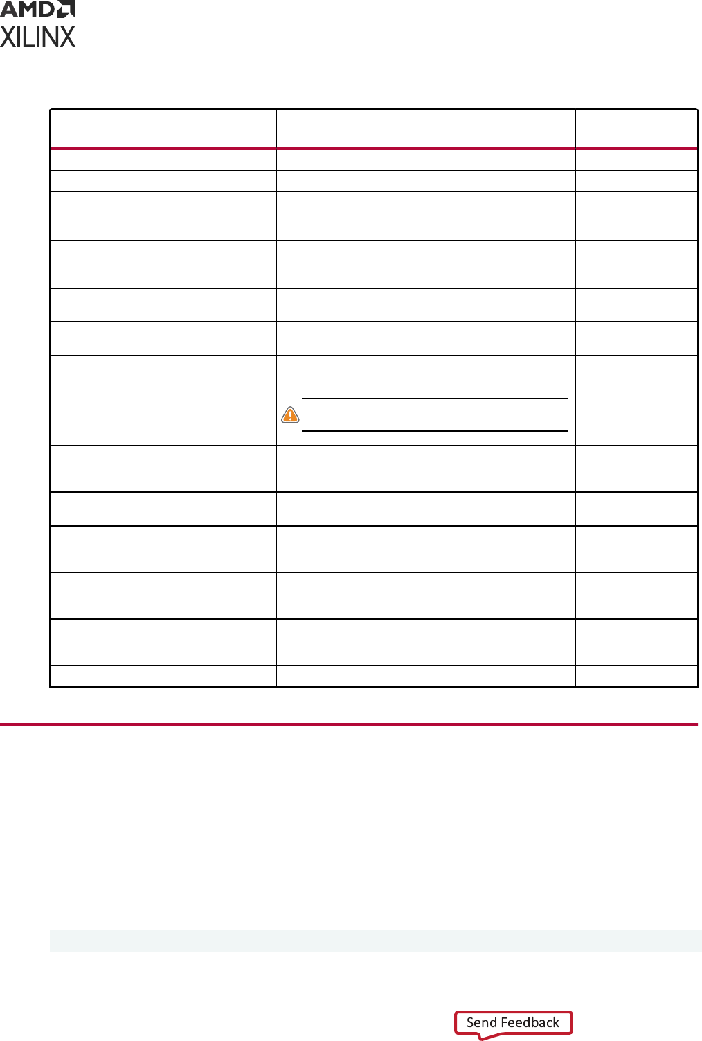
Table 15: xelab, xvhd, and xvlog Command Options (cont'd)
Command Option Description
Used by
Command
-ignore_assertions
Ignore SystemVerilog concurrent assertions. xelab
-ignore_coverage
Ignore SystemVerilog functional coverage. xelab
-cov_db_dir <arg>
Functional coverage database dump directory. The
coverage data is present under <arg>/xsim.covdb/
<cov_db_name> directory. Default is ./.
xelab
-cov_db_name <arg>
Functional coverage database name. The coverage data
is present under <cov_db_dir>/xsim.covdb/<arg>
directory. Default is a snapshot name.
xelab
-uvm_version <arg>
Specify UVM version (default 1.2). Parsing Design Files,
xvhdl and xvlogxelab
-report_assertion_pass
Report SystemVerilog Concurrent Assertions Pass, even
if there is no pass action block.
xelab
-dup_entity_as_module
Enable support for hierarchical references inside the
Verilog hierarchy in mixed language designs.
CAUTION! This may cause significant slow down of
compilation.
xelab
-cc_celldefines
Specify if code coverage information needs to be
captured for libs/modules with cell define attribute set.
OFF by default.
xelab
-cc_libs
Specify if code coverage information needs to be
captured for all the libraries specified. OFF by default.
xelab
-cc_type arg
Specify options for generating Code Coverage Statistics
-bcesfxt. (s)Statement Coverage, (b)Branch Coverage,
(c)Condition Coverage Supported.
xelab
-cc_db arg
Code coverage database will be saved inside
<cc_dir_argvalue>/xsim.codecov/<cc_db_argvalue>.
Default is SnapshotName.
xelab
-cc_dir arg
Code coverage database will be saved under the dir
<cc_dir_argvalue>/xsim.codeCov/<cc_db_argvalue>.
Default is ./xsim.codecov/.
xelab
-ignore_localparam_override
Ignore localparam override xelab
Simulating the Design Snapshot, xsim
The xsim command loads a simulaon snapshot to eect a batch mode simulaon or provides a
workspace (GUI) and/or a Tcl-based interacve simulaon environment.
xsim Executable Syntax
The command syntax is as follows:
xsim <options> <snapshot>
Chapter 7: Simulating in Batch or Scripted Mode in Vivado Simulator
UG900 (v2022.1) April 21, 2022 www.xilinx.com
Vivado Design Suite User Guide: Logic Simulation 155
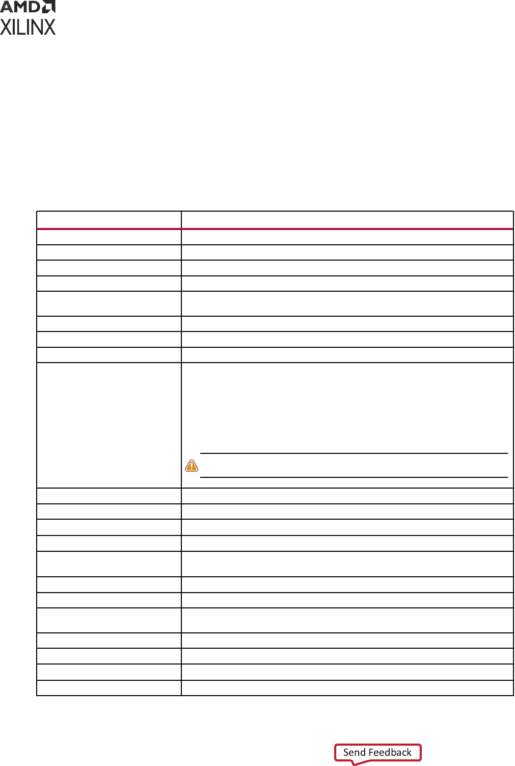
Where:
• xsim is the command.
• <options> are the opons specied in the following table.
• <snapshot> is the simulaon snapshot.
xsim Executable Options
Table 16: xsim Executable Command Options
xsim Option Description
-f [-file] <filename>
Load the command line options from a file.
-g [-gui]
Run with interactive workspace.
-h [-help]
Print help message to screen.
-log <filename>
Specify the log file name.
-maxdeltaid arg (=-1)
Specify the maximum delta number. Report an error if it exceeds maximum
simulation loops at the same time.
-maxlogsize arg (=-1)
Set the maximum size a log file can reach in MB. The default setting is unlimited.
-ieeewarnings
Enable warnings from VHDL IEEE functions.
-nolog
Suppresses log file generation.
-nosignalhandlers
Disables the installation of OS-level signal handlers in the simulation. For
performance reasons, the simulator does not check explicitly for certain conditions,
such as an integer division by zero, that could generate an OS-level fatal run time
error. Instead, the simulator installs signal handlers to catch those errors and
generates a report.
With the signal handlers disabled, the simulator can run in the presence of such
security software, but OS-level fatal errors could crash the simulation abruptly with
little indication of the nature of the failure.
CAUTION! Use this option only if your security software prevents the simulator
from running successfully.
-onfinish <quit|stop>
Specify the behavior at end of simulation.
-onerror <quit|stop>
Specify the behavior upon simulation run time error.
-R [-runall]
Runs simulation till end (such as do 'run all;quit').
-stats
Display memory and CPU stats upon exiting.
-testplusarg <arg>
Specify plusargs to be used by $test$plusargs and $value$plusargs system
functions.
-t [-tclbatch] <filename>
Specify the Tcl file for batch mode execution.
-tp
Enable printing to screen of hierarchical names of process being executed.
-tl
Enable printing to screen of file name and line number of statements being
executed.
-wdb <filename.wdb>
Specify the waveform database output file.
-version
Print the compiler version to screen.
-view <wavefile.wcfg>
Open a wave configuration file. Use this switch together with -gui switch.
-protoinst
Specify a .protoinst file for protocol analysis.
Chapter 7: Simulating in Batch or Scripted Mode in Vivado Simulator
UG900 (v2022.1) April 21, 2022 www.xilinx.com
Vivado Design Suite User Guide: Logic Simulation 156
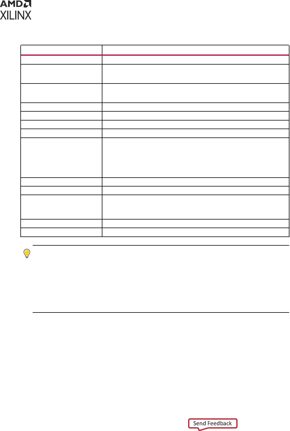
Table 16: xsim Executable Command Options (cont'd)
xsim Option Description
-sv_seed
Seed for SystemVerilog constraint random.
-cov_db_dir
Functional coverage database dump directory. The coverage data is present under
<arg>/xsim.covdb/<cov_db_name> directory. Default is ./ or inherits the value set in
xelab.
-cov_db_name
Functional coverage database name. The coverage data will be present under
<cov_db_dir>/xsim.covdb/<arg> directory. Default is snapshot name or inherits the
value set in xelab.
-downgrade_error2info
Downgrade the severity level of the HDL messages from Error to Info.
-downgrade_error2warning
Downgrade the severity level of the HDL messages from Error to Warning.
-downgrade_fatal2info
Downgrade the severity level of the HDL messages from Fatal to Info.
-downgrade_fatal2warning
Downgrade the severity level of the HDL messages from Fatal to Warning.
-downgrade_severity
Downgrade the severity level of the HDL messages. Following are the choices:
• error2warning
• error2info
• fatal2warning
• fatal2info
-ignore_assertions
Ignore SystemVerilog concurrent assertions.
-ignore_coverage
Ignore SystemVerilog functional coverage.
-ignore_feature
Ignore the effect of a specific HDL feature or construct. Following are the choices:
• assertion
• coverage
-tempDir
Specify the temporary directory name.
-autoloadwcfg
Load already saved waveform configuration file.
TIP: When running the
xelab
,
xsc
,
xsim
,
xvhdl
,
xcrg
, or
xvlog
commands in batch les or scripts,
it might also be necessary to dene the XILINX_VIVADO environment variable to point to the installaon
hierarchy of the Vivado Design Suite. To set the XILINX_VIVADO variable, add one of the following to your
script or batch le:
• On Windows: set XILINX_VIVADO=<vivado_install_area>/Vivado/<version>
• On Linux: setenv XILINX_VIVADO vivado_install_area>/Vivado/<version>
• Where <version> is the version of Vivado tools you are using: 2014.3, 2014.4, 2015.1, etc
Functional Coverage Report Generator
Vivado simulator provides a ulity using which you can generate the funconal coverage report
either in text or html format. The Xilinx Coverage Report Generator (XCRG) can also be used for
merging mulple coverage databases into a single database.
Chapter 7: Simulating in Batch or Scripted Mode in Vivado Simulator
UG900 (v2022.1) April 21, 2022 www.xilinx.com
Vivado Design Suite User Guide: Logic Simulation 157

Table 17: xcrg Command Options and Description
xcrg Option Description
-db_name arg
Name of the database inside xsim.covdb. If unspecified all databases present in the
directory are used.
-dir arg
Path where the xsim.covdb database directory is located. Default is ./xsim.covdb.
-file arg
Specify file with location of the coverage databases to be restored.
-h
Print help message and exit.
-help
Print help message and exit.
-merge_db_name arg
Name of the merged database. Default is xcrg_mdb.
-merge_dir arg
Directory where the merged database is saved. Default is ./xsim.covdb.
-nolog
Suppresses the log file generation.
-report_dir arg
Directory where the coverage database and the report are saved. Default is ./
xcrg_report.
-report_format arg
Specify the desired format of the coverage report html or text or all. Default is html.
-log arg
Specify the file name which has the log saved. Default is xcrg.log.
-version
Print the version of XCRG and exit.
-cc_db <arg>
Specify the DB Name (Snapshot Name) which is used to save the code coverage
database. Code coverage database can be restored from <cc_dir_argvalue>/
xsim.codeCov/<cc_db_argvalue>.
-cc_dir <arg>
Specify the directory where the code coverage information database is saved. Code
coverage database can be restored from <cc_dir_argvalue>/xsim.codeCov/
<cc_db_argvalue>. Default is ./xsim.CodeCov/.
-cc_fullfile
Show the entire file in the code coverage report. By default this is OFF for files more
than 50000 lines and only the file's module contents are shown.
-cc_report <arg>
Directory where the code coverage HTML report is saved. Default is
xcrg_code_cov_report.
-merge_cc
Merge the code coverage databases specified and create a output merged code
coverage database.
-cc_instancescount <arg>
Specify the maximum number of instances shown in the code coverage report. Default
is 100.
xcrg Example Syntax
xcrg -h
xcrg -file /path/to/file
xcrg -file /path/to/file -db_name work.top
xcrg -dir /path/to/abc
xcrg -dir ./abc -report_dir def -report_format html
xcrg -dir ./abc -db_name work.top -report_dir def -report_format html
xcrg -dir /path/to/abc -db_name work.top -report_dir def -report_format text
xcrg -merge_dir m
xcrg -merge_db_name xyz -report_dir def
xcrg -report_format html -nolog
xcrg -report_format html -log xcrgOutput.log
xcrg -cc_db a1 -cc_dir ./
xcrg -cc_report abc -cc_db work.testbench -cc_dir ./xsim.codeCov/
Chapter 7: Simulating in Batch or Scripted Mode in Vivado Simulator
UG900 (v2022.1) April 21, 2022 www.xilinx.com
Vivado Design Suite User Guide: Logic Simulation 158
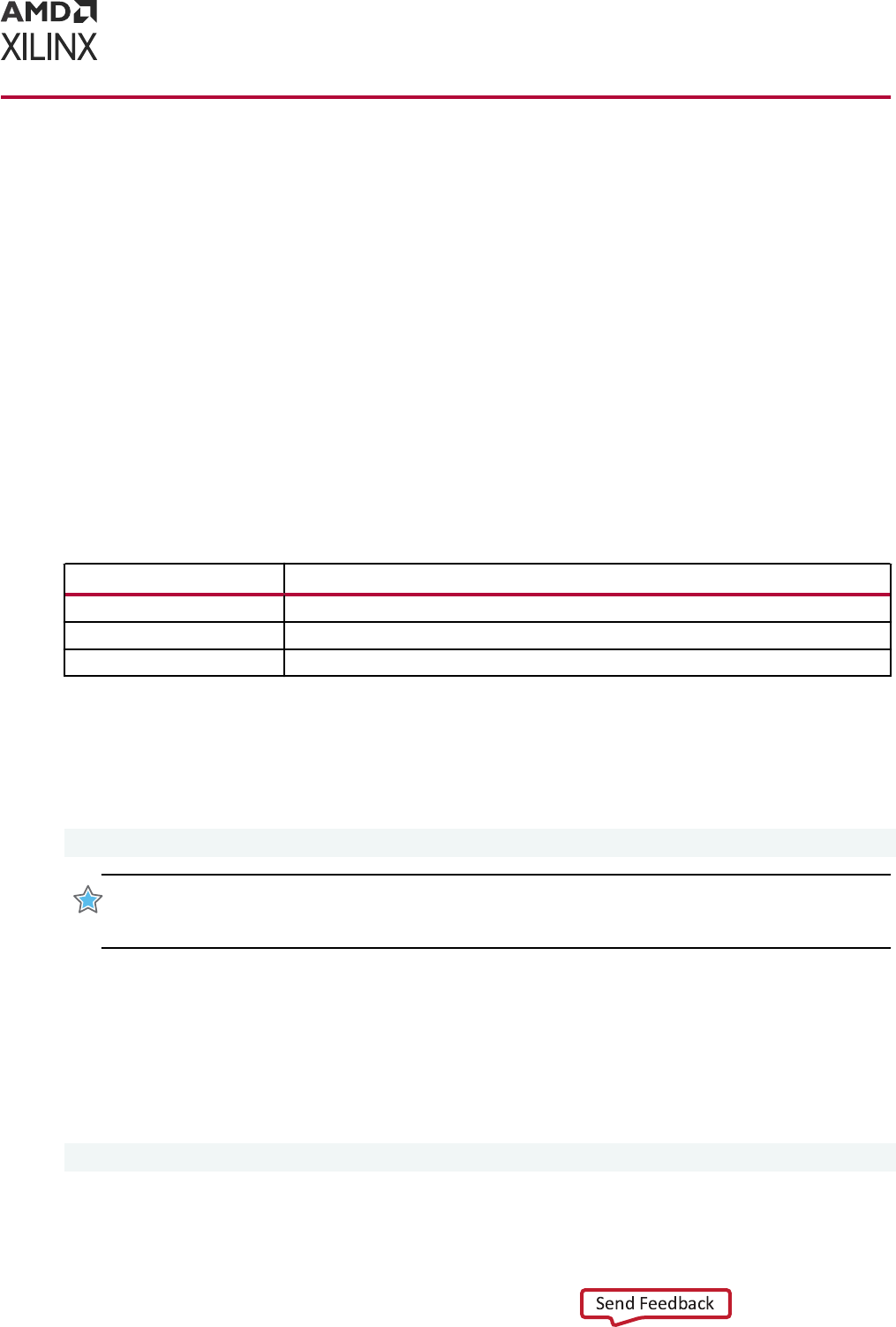
Example of Running Vivado Simulator in
Standalone Mode
When running the Vivado simulator in standalone mode, you can execute commands to:
• Analyze the design le
• Elaborate the design and create a snapshot
• Open the Vivado simulator workspace and wave conguraon le(s) and run simulaon
Step 1: Analyzing the Design File
To begin, analyze your HDL source les by type, as shown in the table below. Each command can
take mulple les.
Table 18: File Types and Associated Commands for Design File Analysis
File Type Command
Verilog
xvlog <VerilogFileName(s)>
SystemVerilog
xvlog -sv <SystemVerlilogFileName(s)>
VHDL
xvhdl <VhdlFileName(s)>
Step 2: Elaborating and Creating a Snapshot
Aer analysis, elaborate the design and create a snapshot for simulaon using the xelab
command:
xelab <topDesignUnitName> -debug typical
IMPORTANT!
You can provide mulple top-level design unit names with
xelab
. To use the Vivado
simulator workspace for purposes similar to those used during
launch_simulation
, you must set
debug level to
typical
.
Step 3: Running Simulation
Aer successful compleon of the xelab phase, the Vivado simulator creates a snapshot used
for running simulaon.
To invoke the Vivado simulator workspace, use the following command:
xsim <SnapShotName> -gui
Chapter 7: Simulating in Batch or Scripted Mode in Vivado Simulator
UG900 (v2022.1) April 21, 2022 www.xilinx.com
Vivado Design Suite User Guide: Logic Simulation 159

To open the wave cong le:
xsim <SnapShotName> -view <wcfg FileName> -gui
You can provide mulple wcfg les using mulple -view ags. For example:
xsim <SnapShotName> -view <wcfg FileName> -view <wcfg FileName>
Project File (.prj) Syntax
Note: The project le discussed here is a Vivado simulator text-based project le. It is not the same as the
project le (.xpr) created by the Vivado Design Suite.
To parse design les using a project le, create a text le called <proj_name>.prj, and use the
syntax shown below inside the project le.
verilog <work_library> <file_names>... [-d <macro>]...[-i
<include_path>]...
vhdl <work_library> <file_name>
sv <work_library> <file_name>
vhdl2008 <work_library> <file_name>
Where:
<work_library>: Is the library into which the HDL les on the given line are to be compiled.
<file_names>: Are Verilog source les. You can specify mulple Verilog les per line.
<file_name>: Is a VHDL source le; specify only one VHDL le per line.
1. For Verilog or SystemVerilog: [-d <macro>] provides you the opon to dene one or more
macros.
2. For Verilog or SystemVerilog: [-i <include_path>] provides you the opon to dene
one or more <include_path> directories.
Chapter 7: Simulating in Batch or Scripted Mode in Vivado Simulator
UG900 (v2022.1) April 21, 2022 www.xilinx.com
Vivado Design Suite User Guide: Logic Simulation 160

Predefined Macros
XILINX_SIMULATOR is a Verilog predened-macro. The value of this macro is 1. Predened
macros perform tool-specic funcons, or idenfy which tool to use in a design ow. The
following is an example usage:
`ifdef VCS
// VCS specific code
`endif
`ifdef INCA
// NCSIM specific code
`endif
`ifdef MODEL_TECH
// MODELSIM specific code
`endif
`ifdef XILINX_ISIM
// ISE Simulator (ISim) specific code
`endif
`ifdef XILINX_SIMULATOR
// Vivado Simulator (XSim) specific code
`endif
`ifdef _VCP
//Aldec specific code
`endif
Library Mapping File (xsim.ini)
The HDL compile programs, xvhdl, xvlog, and xelab, use the xsim.ini conguraon le to
nd the denions and physical locaons of VHDL and Verilog logical libraries.
The compilers aempt to read xsim.ini from these locaons in the following order:
1. xsim.ini in current working directory
2. User-le specied through the -initfile switch. If -initfile is not specied, the
program searches for xsim.ini in the current working directory.
3. <Vivado_Install_Dir>/data/xsim
The xsim.ini le has the following syntax:
<logical_library1> = <physical_dir_path1>
<logical_library2> = <physical_dir_path2>
Chapter 7: Simulating in Batch or Scripted Mode in Vivado Simulator
UG900 (v2022.1) April 21, 2022 www.xilinx.com
Vivado Design Suite User Guide: Logic Simulation 161

The following is an example xsim.ini le:
std=<Vivado_Install_Area>/xsim/vhdl/std
ieee=<Vivado_Install_Area>/xsim/vhdl/ieee
vl=<Vivado_Install_Area>/xsim/vhdl/vl
ieee_proposed=$RDI_DATADIR/xsim/vhdl/ieee_proposed
synopsys=<Vivado_Install_Area>/xsim/vhdl/synopsys
uvm=<Vivado_Install_Area>/xsim/system_verilog/uvm
unisim=<Vivado_Install_Area>/xsim/vhdl/unisim
unimacro=<Vivado_Install_Area>/xsim/vhdl/unimacro
unifast=<Vivado_Install_Area>/xsim/vhdl/unifast
simprims_ver=<Vivado_Install_Area>/xsim/verilog/simprims_ver
unisims_ver=<Vivado_Install_Area>/xsim/verilog/unisims_ver
unimacro_ver=<Vivado_Install_Area>/xsim/verilog/unimacro_ver
unifast_ver=<Vivado_Install_Area>/xsim/verilog/unifast_ver
secureip=<Vivado_Install_Area>/xsim/verilog/secureip
work=./work
The xsim.ini le has the following features and limitaons:
• There must be no more than one library path per line inside the xsim.ini le.
• If the directory corresponding to the physical path does not exist, xvhd or xvlog creates it
when the compiler rst tries to write to that path.
• You can describe the physical path in terms of environment variables. The environment
variable must start with the $ character.
• The default physical directory for a logical library is xsim/<language>/
<logical_library_name>, for example, a logical library name of:
<Vivado_Install_Area>/xsim/vhdl/unisim
• File comments must start with --.
Note: From 2018.2 release onwards, Xilinx provides two init les named as xsim.ini and
xsim_legacy.ini. The xsim_legacy.ini le is similar to xsim.ini of older version. It contains
mapping for UNISIM library while the new xsim.ini le contains mapping for all the les of UNISIM
library along with the mapping for pre-compiled IP.
Running Simulation Modes
You can run any mode of simulaon from the command line. The following subsecons illustrate
and describe the simulaon modes when run from the command line.
Behavioral Simulation
The following gure illustrates the behavioral simulaon process:
Chapter 7: Simulating in Batch or Scripted Mode in Vivado Simulator
UG900 (v2022.1) April 21, 2022 www.xilinx.com
Vivado Design Suite User Guide: Logic Simulation 162
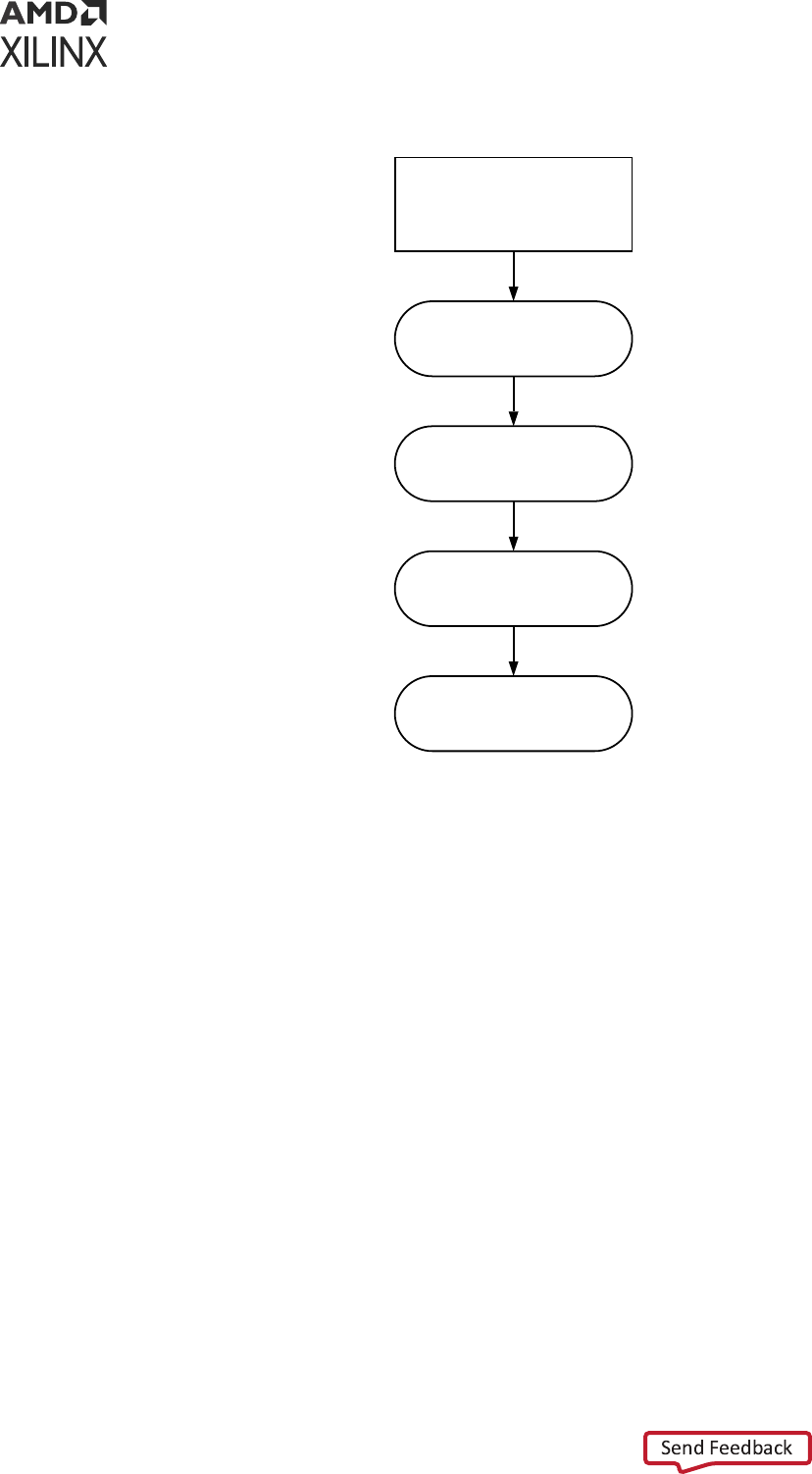
Figure 51: Behavioral Simulation Process
Gather Files
Parse Using XVLOG/XVHDL
Compile and Elaborate Using
XELAB (Create Snapshot)
Debug on Waveform
Execute Using
XSIM <snapshot>
X23705-021420
To run behavioral simulaon from within the Vivado Design Suite, use the Tcl command:
launch_simulation -mode behavioral.
Running Post-Synthesis and Post-Implementation
Simulations
At post-synthesis and post-implementaon, you can run a funconal or a Verilog ming
simulaon. The following gure illustrates the post-synthesis and post-implementaon
simulaon process:
Chapter 7: Simulating in Batch or Scripted Mode in Vivado Simulator
UG900 (v2022.1) April 21, 2022 www.xilinx.com
Vivado Design Suite User Guide: Logic Simulation 163
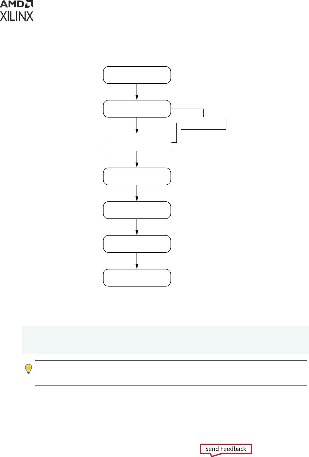
Figure 52: Post-Synthesis and Post-Implementation Simulation
Run Synthesis or Implementation
Parse Using xvlog/xvhdl
Simulation Using
xsim <snapshot>
Create Netlist
write_verilog or write_vhdl
Post-Synthesis
Post-Implementation
Simulation
Gather Files
(Create Project File )
Compile and Elaborate
Using xelab
Debug in Waveform
Or Self-checking Test Bench
X12985
For Timing Simulation
write_sdf
The following is an example of running a post-synthesis funconal simulaon from the command
line:
synth_design -top top -part xc7k70tfbg676-2
open_run synth_1 -name netlist_1
write_verilog -mode funcsim test_synth.v
launch_simulation
TIP:
When you run a post-synthesis or post-implementaon ming simulaon, you must run the
write_sdf
command aer the
write_verilog
command, and the appropriate annotate command
is needed for elaboraon and simulaon.
Chapter 7: Simulating in Batch or Scripted Mode in Vivado Simulator
UG900 (v2022.1) April 21, 2022 www.xilinx.com
Vivado Design Suite User Guide: Logic Simulation 164

Using Tcl Commands and Scripts
You can run Tcl commands on the Tcl Console individually, or batch the commands into a Tcl
script to run simulaon.
Using a -tclbatch File
You can type simulaon commands into a Tcl le, and reference the Tcl le with the following
command: -tclbatch <filename>
Use the -tclbatch opon to contain commands within a le and execute those command as
simulaon starts. For example, you can have a le named run.tcl that contains the following:
run 20ns
id="ag415279">current_time
quit
Then launch simulaon as follows:
xsim <snapshot> -tclbatch run.tcl
You can set a variable to represent a simulaon command to quickly run frequently used
simulaon commands.
Launching Vivado Simulator from the Tcl Console
The following is an example of Tcl commands that create a project, read in source les, launch the
Vivado simulator, do placing and roung, write out an SDF le, and re-launch simulaon.
Vivado -mode Tcl
Vivado% create_project prj1
Vivado% read_verilog dut.v
Vivado% synth_design -top dut
Vivado% launch_simulation -simset sim_1 -mode post-synthesis -type
functional
Vivado% place_design
Vivado% route_design
Vivado% write_verilog -mode timesim -sdf_anno true -sdf_file postRoute.sdf
postRoute_netlist.v
Vivado% write_sdf postRoute.sdf
Vivado% launch_simulation -simset sim_1 -mode post-implementation -type
timing
Vivado% close_project
Chapter 7: Simulating in Batch or Scripted Mode in Vivado Simulator
UG900 (v2022.1) April 21, 2022 www.xilinx.com
Vivado Design Suite User Guide: Logic Simulation 165

export_simulation
Export a simulaon script le for the target simulator. The generated script will contain simulator
commands for compiling, elaborang and simulang the design.
This command will retrieve the simulaon compile order of specied objects, and export this
informaon in a shell script with the compiler commands and default opons for the target
simulator. The specied object can be either a simulaon leset or an IP. If you want to run
simulaon outside Vivado IDE, export_simulation can be used in place of
launch_simulation -scripts_only to generate scripts le.
export_simulation [-simulator <arg>] [-of_objects <arg>]
[-ip_user_files_dir <arg>] [-ipstatic_source_dir <arg>]
[-lib_map_path <arg>] [-script_name <arg>]
[-directory <arg>] [-runtime <arg>] [-define <arg>]
[-generic <arg>] [-include <arg>] [-use_ip_compiled_libs]
[-absolute_path] [-export_source_files]
[-generate_hier_access] [-32bit] [-force] [-quiet]
[-verbose][-gcc_install_path <arg>] [-more_options <arg>]
Usage
Table 19: export_simulation Options
Name Description
[-simulator]
Simulator for which the simulation script will be created. Allowed values are all,
xsim, modelsim, questa, vcs, xcelium, riviera, and activehdl.
Default: all
[-of_objects]
Export simulation script for the specified object.
Default: None
[-lib_map_path]
Precompiled simulation library directory path. If not specified, follow the
instructions in the generated script header to manually provide the simulation
library mapping information.
Default: Empty
[-script_name]
Output shell script filename. If not specified, then file with a default name will be
created.
Default: top_module.sh
[-directory]
Directory where the simulation script will be generated.
Default: export_sim
[-runtime]
Run simulation for this time.
Default: full simulation run or until a logical break or finish condition
[-absolute_path]
Make all file paths absolute with respect to the reference directory.
[-export_source_files]
Copy IP/BD design files to output directory.
[-32bit]
Perform 32-bit compilation.
[-force]
Overwrite previous files.
[-quiet]
Ignore command errors.
[-verbose]
Suspend message limits during command execution.
Chapter 7: Simulating in Batch or Scripted Mode in Vivado Simulator
UG900 (v2022.1) April 21, 2022 www.xilinx.com
Vivado Design Suite User Guide: Logic Simulation 166

Table 19: export_simulation Options (cont'd)
Name Description
[-ip_user_files_dir]
Directory path to exported IP/BD user files (for static, dynamic and data files).
Default: Empty
[-ipstatic_source_dir]
Directory path to the exported IP/BD static files.
Default: Empty
[-define]
Read Verilog defines from the list specified with this switch.
Default: Empty
[-generic]
Read VHDL generics from the list specified with this switch.
Default: Empty
[-include]
Read include directory paths from the list specified with this switch.
Default: Empty
[-use_ip_compiled_libs]
Reference pre-compiled IP static library during compilation. This switch requires -
ip_user_files_dir and -ipstatic_source_dir switches also for generating
scripts using pre-compiled IP library.
[-generate_hier_access]
Extract path for hierarchical access simulation
[-gcc_install_path]
GNU compiler installation directory path for the g++/gcc executables.
Default: Empty
[-more_options]
Pass specified options to the simulator tool.
Default: Empty
Description
Export a simulaon script le for the target simulator (please see the list of supported simulators
below). The generated script will contain simulator commands for compiling, elaborang and
simulang the design.
The command will retrieve the simulaon compile order of specied objects, and export this
informaon in a shell script with the compiler commands and default opons for the target
simulator. The specied object can be either a simulaon leset, IP or a BD (block design).
If the object is not specied, then this command will generate the script for the acve simulaon
top. Any Verilog include directories or le paths for the les containing Verilog dene
statements will be added to the compiler command line.
By default, the design source le and include directory paths in the compiler command line will
be set relave to the reference_dir variable that is set in the generated script. To make these
paths absolute, specify the -absolute_path switch.
The command will also copy data les (if any) from the leset, or from an IP, to the output
directory. If the design contains Verilog sources, then the generated script will also copy the
glbl.v le from the soware installaon path to the output directory.
A default .do le that is used in the compiler commands in the simulaon script for the target
simulator, will be wrien to the output directory.
Chapter 7: Simulating in Batch or Scripted Mode in Vivado Simulator
UG900 (v2022.1) April 21, 2022 www.xilinx.com
Vivado Design Suite User Guide: Logic Simulation 167

Note: In order to perform simulaon with the generated script, the simulaon libraries must be compiled
rst using the compile_simlib Tcl command. The compiled library directory path must be specied
when generang this script. The generated script will automacally include the setup les for the target
simulator from the compiled library directory.
Supported Simulators
• Vivado simulator (xsim)
• ModelSim Simulator (modelsim)
• Questa Advanced Simulator (questa)
• Verilog Compiler Simulator (vcs)
• Riviera-PRO Simulator (riviera)
• Acve-HDL Simulator (acvehdl)
• Cadence Xcelium Parallel Simulator (xcelium)
Arguments
• -of_objects: (Oponal) Specify the target object for which the simulaon script le needs
to be generated. The target object can be either a simulaon leset (simset) or an IP. If this
opon is not specied then this command will generate le for the current simulaon leset.
• -lib_map_path: (Oponal) Specify path to the Xilinx pre-compiled simulaon library for the
selected simulator. The simulaon library is compiled using compile_simlib. See the
header secon in the generated script for more informaon. If this switch is not specied,
then the generated script will not reference the pre-compiled simulaon library and the stac
IP les will be locally compiled.
• -script_name: (Oponal) Specify name of the generated script. Default name is
<simulation_top>.sh. If the -of_objects switch is specied, then the default syntax of the
script will be as follows:
-of_objects [current_fileset -simset] .sh
-of_objects [get_ips ] .sh
-of_objects [get_files .xci] .sh
-of_objects [get_files .bd] .sh
• -absolute_path: (Oponal) Specify this opon to make source and include directory paths
absolute. By default, all paths are set relave to the output directory specied with the -
directory switch.
• -32bit: (Oponal) Specify this opon to perform 32-bit simulaon. If this opon is not
specied then by default 64-bit opon will be added to the simulaon command line.
• -force: (Oponal) Overwrite an exisng script le of the same name. If the script le already
exists, the tool returns an error unless the -force argument is specied.
Chapter 7: Simulating in Batch or Scripted Mode in Vivado Simulator
UG900 (v2022.1) April 21, 2022 www.xilinx.com
Vivado Design Suite User Guide: Logic Simulation 168

• -directory: (Required) Specify the directory path where the script le will be exported.
• -simulator: (Required) Specify the target simulator name for the simulaon script. The valid
simulators names are xsim, modelsim, questa, and vcs (or vcs_mx).
• -quiet: (Oponal) Execute the command quietly, ignoring any command line errors and
returning no messages. The command also returns TCL_OK regardless of any errors
encountered during execuon.
• -verbose: (Oponal) Temporarily override any message limits and return all messages from
this command.
• -generate_hier_access: (Oponal) Extract path for hierarchical access simulaon.
• -runtime: (Oponal) Specify simulaon run-me.
• -define: (Oponal) Specify the list of verilog denes used in the design.
• -generic: (Oponal) Specify the list of VHDL generics used in the design.
• -include: (Oponal) Specify the list of include directory paths for verilog include les in the
design.
• -export_source_files: (Oponal) Specify this opon to copy the IP design les to the
generated script directory in a sub-directory named srcs. The generated script will reference
the design les from this srcs directory.
export_ip_user_files
Generate and export IP/IP integrator user les from a project. This can be scoped to work on one
or more IPs.
Syntax
export_ip_user_files [-of_objects <arg>] [-ip_user_files_dir <arg>]
[-ipstatic_source_dir <arg>] [-lib_map_path <arg>]
[-no_script] [-sync] [-reset] [-force] [-quiet]
[-verbose]
Returns: List of les that were exported.
Chapter 7: Simulating in Batch or Scripted Mode in Vivado Simulator
UG900 (v2022.1) April 21, 2022 www.xilinx.com
Vivado Design Suite User Guide: Logic Simulation 169
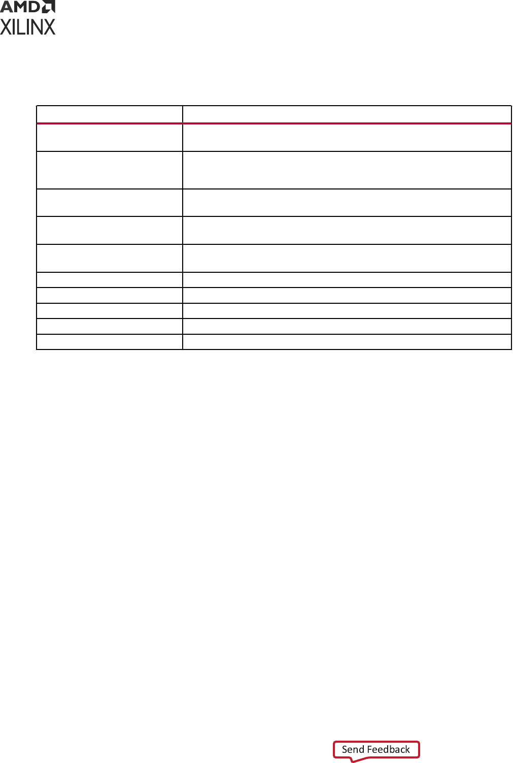
Usage
Table 20: export_ip_user_files
Name Description
[-of_objects]
IP, IP integrator or a fileset.
Default: None
[-ip_user_files_dir]
Directory path to simulation base directory (for static, dynamic, wrapper, netlist,
script, and MEM files).
Default: None
[-ipstatic_source_dir]
Directory path to the static IP files.
Default: None
[-lib_map_path]
Compiled simulation library directory path.
Default: Empty
[-no_script]
Do not export simulation scripts.
Default: 1
[-sync]
Delete IP/IP integrator dynamic and simulation script files.
[-reset]
Delete all IP/IP integrator static, dynamic and simulation script files.
[-force]
Overwrite files.
[-quiet]
Ignore command errors.
[-verbose]
Suspend message limits during command execution.
Description
Export IP user les repository with stac, dynamic, netlist, Verilog/VHDL stubs and memory
inializaon les.
Arguments
• -of_objects: (Oponal) Specify the target object for which the IP stac and dynamic les
needs to be exported.
• -ip_user_files_dir: (Oponal) Directory path to IP user les base directory (for dynamic
and other IP non stac les). By default, if this switch is not specied then this command will
use the path specied with the IP.USER_FILES_DIR project property value.
• -ipstatic_source_dir: (Oponal) Directory path to the stac IP les. By default, if this
switch is not specied then this command will use the path specied with the
SIM.IPSTATIC_SOURCE_DIR project property value.
Note: If the -ip_user_files_dir switch is specied, by default the IP stac les will be exported
under the sub-directory with the name ipstatic. If this switch is specied with -
ipstatic_source_dir, then the IP stac les will be exported in the path specied with the -
ipstatic_source_dir switch.
• -clean_dir: (Oponal) Delete all les from central directory (including stac, dynamic and
other les)
Chapter 7: Simulating in Batch or Scripted Mode in Vivado Simulator
UG900 (v2022.1) April 21, 2022 www.xilinx.com
Vivado Design Suite User Guide: Logic Simulation 170

Examples
The following command will export char_fifo IP dynamic les to <project>/
<project>.ip_user_files/ip/char_fifo directory and char_fifo IP stac les to
<project>/<project>.ip_user_files/ipstatic directory:
% export_ip_user_files -of_objects [get_ips char_fifo]
Chapter 7: Simulating in Batch or Scripted Mode in Vivado Simulator
UG900 (v2022.1) April 21, 2022 www.xilinx.com
Vivado Design Suite User Guide: Logic Simulation 171

Appendix A
Compilation, Elaboration,
Simulation, Netlist, and Advanced
Options
From the Vivado IDE Flow Navigator, you can right-click Simulaon, and select Simulaon
Sengs to open the simulaon sengs in the Sengs dialog box. From the Simulaon sengs,
you can set various compilaon, elaboraon, simulaon, netlist, and advanced opons.
Compilation Options
The Compilaon tab denes and manages compiler direcves, which are stored as properes on
the simulaon leset and used by the xvlog and xvhdl ulies to compile Verilog and VHDL
source les for simulaon.
Vivado Simulator Compilation Options
Table 21: Vivado Simulator Compilation Options
Option Description
Verilog options Browse to set Verilog include path and to define macro
Generics/Parameters options Specify or browse to set the generic/parameter value
xsim.compile.tcl.pre
Tcl file containing set of commands that should be invoked before launch of
compilation
xsim.compile.xvlog.nosort
Do not sort Verilog file during compilation
xsim.compile.xvhdl.nosort
Do not sort VHDL file during compilation
xsim.compile.xvlog.relax
Relax strict Verilog and SystemVerilog language checking rules
xsim.compile.xvhdl.relax
Relax strict VHDL language checking rules
xsim.compile.xvlog.more_options
More XVLOG compilation options
xsim.compile.xvhdl.more_options
More XVHDL compilation options
xsim.compile.xsc.more_options
More XSC compilation options
Appendix A: Compilation, Elaboration, Simulation, Netlist, and Advanced Options
UG900 (v2022.1) April 21, 2022 www.xilinx.com
Vivado Design Suite User Guide: Logic Simulation 172

Questa Advanced Simulator Compilation Options
Table 22: Questa Advanced Simulator Compilation Options
Option Description
Verilog options Browse to set Verilog include path and to define macro
Generics/Parameters options Specify or browse to set the generic/parameter value
questasim.compile.tcl.pre TCL file containing set of commands that should be invoked before
launch of compilation
questasim.compile.vhdl_syntax Specify VHDL syntax
questasim.compile.use_explicit_decl Log all signals
questasim.compile.load_glbl Load GLBL module
questasim.compile.vlog.more_options More VLOG compilation options
questasim.compile.vcom.more_options More VCOM compilation options
questasim.compile.sccom.cores Specify the number of process cores to run in parallel
questasim.compile.sccom.more_options More SCCOM compilation options
ModelSim Simulator Compilation Options
Table 23: ModelSim Compilation Options
Option Description
Verilog options Browse to set Verilog include path and to define macro
Generics/Parameters options Specify or browse to set the generic/parameter value
modelsim.compile.tcl.pre TCL file containing set of commands that should be invoked before launch
of compilation
modelsim.compile.vhdl_syntax Specify VHDL syntax
modelsim.compile.use_explicit_decl Log all signals
modelsim.compile.load_glbl Load GLBL module
modelsim.compile.vlog.more_options More VLOG compilation options
modelsim.compile.vcom.more_options More VCOM compilation options
VCS Simulator Compilation Options
Table 24: VCS Simulator Compilation Options
Option Description
Verilog options Browse to set the Verilog include path and to define macro
Generics/Parameters options Specify or browse to set the generic/parameter values
vcs.compile.tcl.pre TCL file containing set of commands that should be invoked before launch of
compilation
vcs.compile.load_glbl Load GLBL module
vcs.compile.vhdlan.more_options More VHDLAN compilation options
Appendix A: Compilation, Elaboration, Simulation, Netlist, and Advanced Options
UG900 (v2022.1) April 21, 2022 www.xilinx.com
Vivado Design Suite User Guide: Logic Simulation 173
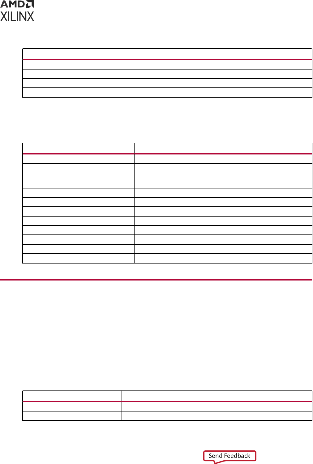
Table 24: VCS Simulator Compilation Options (cont'd)
Option Description
vcs.compile.vlogan.more_options Extra VLOGAN compilation options
vcs.compile.syscan.more_options More SYSCAN compilation options
vcs.compile.g++.more_options More G++ compilation options
vcs.compile.gcc.more_options More GCC compilation options
Xcelium Simulator Compilation Options
Table 25: Xcelium Compilation Options
Options Description
Verilog Options Browse to set Verilog include path and to define macro
Generics/Parameters options Specify or browse to set the generic/parameter value
xcelium.compile.tcl.pre TCL file containing set of commands that should be invoked before the
launch of a compilation
xcelium.compile.v93 Enable VHDL-93 features
xcelium.compile.relax Enable relaxed VHDL interpretation
xcelium.compile.load_glbl Load GLBL module
xcelium.compile.xmvhdl.more_options More XMVHDL compilation options
xcelium.compile.xmvlog.more_options More XMVLOG compilation options
xcelium.compile.xmsc.more_option More XMSC compilation option
xcelium.compile.g++.more_option More G++ compilation option
xcelium.compile.gcc.more_option More GCC compilation option
Elaboration Options
The Elaboraon tab denes and manages elaboraon direcves, which are stored as properes
on the simulaon leset and used by the xelab ulity for elaborang and generang a simulaon
snapshot. Select a property in the table to display a descripon of the property and edit the
value.
Vivado Simulator Elaboration Options
Table 26:
Vivado Simulator Elaboration Options
Option Description
xsim.elaborate.snapshot Specifies the simulation snapshot name
xsim.elaborate.debug_level Choose simulation debug visibility level. By default it is "typical"
Appendix A: Compilation, Elaboration, Simulation, Netlist, and Advanced Options
UG900 (v2022.1) April 21, 2022 www.xilinx.com
Vivado Design Suite User Guide: Logic Simulation 174
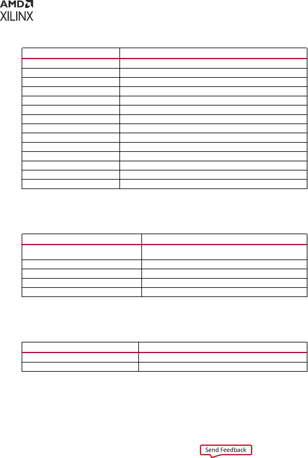
Table 26: Vivado Simulator Elaboration Options (cont'd)
Option Description
xsim.elaborate.relax Relax strict HDL Language checking rules
xsim.elaborate.mt_level Specify number of sub-compilation jobs to run in parallel
xsim.elaborate.load_glbl Load GLBL module
xsim.elaborate.rangecheck Enables run time value range check for VHDL
xsim.elaborate.sdf_delay Specifies sdf timing delay type to be read for use in timing simulation
xsim.elaborate.xelab.more_option More XELAB elaboration options
xsim.elaborate.xsc.more_option More options for XSC during elaboration
xsim.elaborate.coverage.name Specify coverage database name
xsim.elaborate.coverage.dir Specify coverage database directory name
xsim.elaborate.coverage.type Specify coverage type(s) (line branch condition or all)
xsim.elaborate.coverage.library Track std/unisims/retarget libraries
xsim.elaborate.coverage.celldefine Track modules with celldefine attributes
xsim.elaborate.link.sysc Specify SystemC library to bind
xsim.elaborate.link.c Specify C/C++ library to bind
Questa Advanced Simulator Elaboration Options
Table 27: Questa Advanced Simulator Elaboration Options
Option Description
questasim.elaborate.acc Enables access to simulation objects that might be optimized by
default (default: npr)
questasim.elaborate.vopt.more_options More VOPT elaboration options
questasim.elaborate.sccom.more_options More options for sccom during elaboration
questasim.elaborate.link.sysc Specify SystemC library to bind
questasim.elaborate.link.c Specify C/C++ library to bind
ModelSim Simulator Elaboration Options
Table 28: ModelSim Elaboration Options
Option Description
modelsim.elaborate.acc Enables access to simulation objects that might be optimized by default
modelsim.elaborate.vopt.more_options More VOPT elaboration options
Appendix A: Compilation, Elaboration, Simulation, Netlist, and Advanced Options
UG900 (v2022.1) April 21, 2022 www.xilinx.com
Vivado Design Suite User Guide: Logic Simulation 175
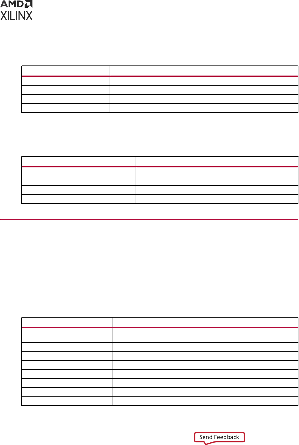
VCS Simulator Elaboration Options
Table 29: VCS Elaboration Options
Option Description
vcs.elaborate.debug_pp Enable post-process debug access
vcs.elaborate.vcs.more_options More VCS elaboration options
vcs.elaborate.link.sysc Specify SystemC library to bind
vcs.elaborate.link.c Specify C/C++ library to bind
Xcelium Simulator Elaboration Options
Table 30: Xcelium Elaboration Options
Option Description
xcelium.elaborate.update Checks if unit is up-to-date before writing
xcelium.elaborate.xmelab.more_options More xmelab elaboration options
xcelium.elaborate.link.sysc Specify SystemC library to bind
xcelium.elaborate.link.c Specify C/C++ library to bind
Simulation Options
The Simulaon tab denes and manages simulaon direcves, which are stored as properes on
the simulaon leset and used by the xsim applicaon for simulang the current project. Select a
property in the table to display a descripon of the property and edit the value.
Vivado Simulator Simulation Options
Table 31: Vivado Simulator Simulation Options
Option Description
xsim.simulate.runtime Specifies simulation run time for the Vivado simulator. Enter blank to load just
the simulation snapshot and wait for user input.
xsim.simulate.tcl.post Tcl file containing set of commands that you want to invoke at end of simulation.
xsim.simulate.log_all_signals Logs all object signals
xsim.simulate.wdb Specifies simulation waveform database file
xsim.simulate.saif Specifies SAIF file name
xsim.simulate.saif_scope Specifies design hierarchy instance name for which power estimation is desired.
xsim.simulate.saif_all_signals Logs all object signals for the design under test for SAIF file generation
xsim.simulate.xsim.more_option More Vivado simulator simulation options
Appendix A: Compilation, Elaboration, Simulation, Netlist, and Advanced Options
UG900 (v2022.1) April 21, 2022 www.xilinx.com
Vivado Design Suite User Guide: Logic Simulation 176

Table 31: Vivado Simulator Simulation Options (cont'd)
Option Description
xsim.simulate.custom_tcl Specify the name of a custom tcl file which will be the source during simulation in
place of a regular Tcl file generated by Vivado
xsim.simulate.add_positional Add positional parameter to XSIM for passing command line argument
xsim.simulate.no_quit Do not quit simulation
Questa Advanced Simulator Simulation Options
Table 32: Questa Advanced Simulator Simulation Options
Option Description
questasim.simulate.runtime Specify simulation run time
questasim.simulate.tcl.post TCL file containing set of commands that you want to invoke at end of
simulation.
questasim.simulate.log_all_signals Log all signals
questasim.simulate.custom_do Specify the name of custom do file
questasim.simulate.custom_udo Specify the name of custom user do file
questa.simulate.ieee_warning Suppresses IEEE warnings
questasim.simulate.sdf_delay Specify the delay type for sdf annotation
questasim.simulate.saif Specify SAIF file
questasim.simulate.saif_scope Specify design hierarchy instance name for which power estimation is
desired
questasim.simulate.vsim.more_option More VSIM simulation options
questa.simulate.custom_wave_do Name of the custom wave.do file which is used in place of a regular Vivado
generated wave.do file
ModelSim Simulator Simulation Options
Table 33: ModelSim Simulation Options
Option Description
modelsim.simulate.runtime Specify simulation run time
modelsim.simulate.tcl.post TCL file containing set of commands that you want to invoke at end of
simulation.
modelsim.simulate.log_all_signals Log all signals
modelsim.simulate.custom_do Specify the name of custom do file
modelsim.simulate.custom_udo Specify the name of custom user do file
modelsim.simulate.sdf_delay Specify the delay type for sdf annotation
modelsim.simulate.ieee_warning Suppresses IEEE warnings
modelsim.simulate.saif Specify SAIF file
modelsim.simulate.saif_scope Specify design hierarchy instance name for which power estimation is
desired
Appendix A: Compilation, Elaboration, Simulation, Netlist, and Advanced Options
UG900 (v2022.1) April 21, 2022 www.xilinx.com
Vivado Design Suite User Guide: Logic Simulation 177
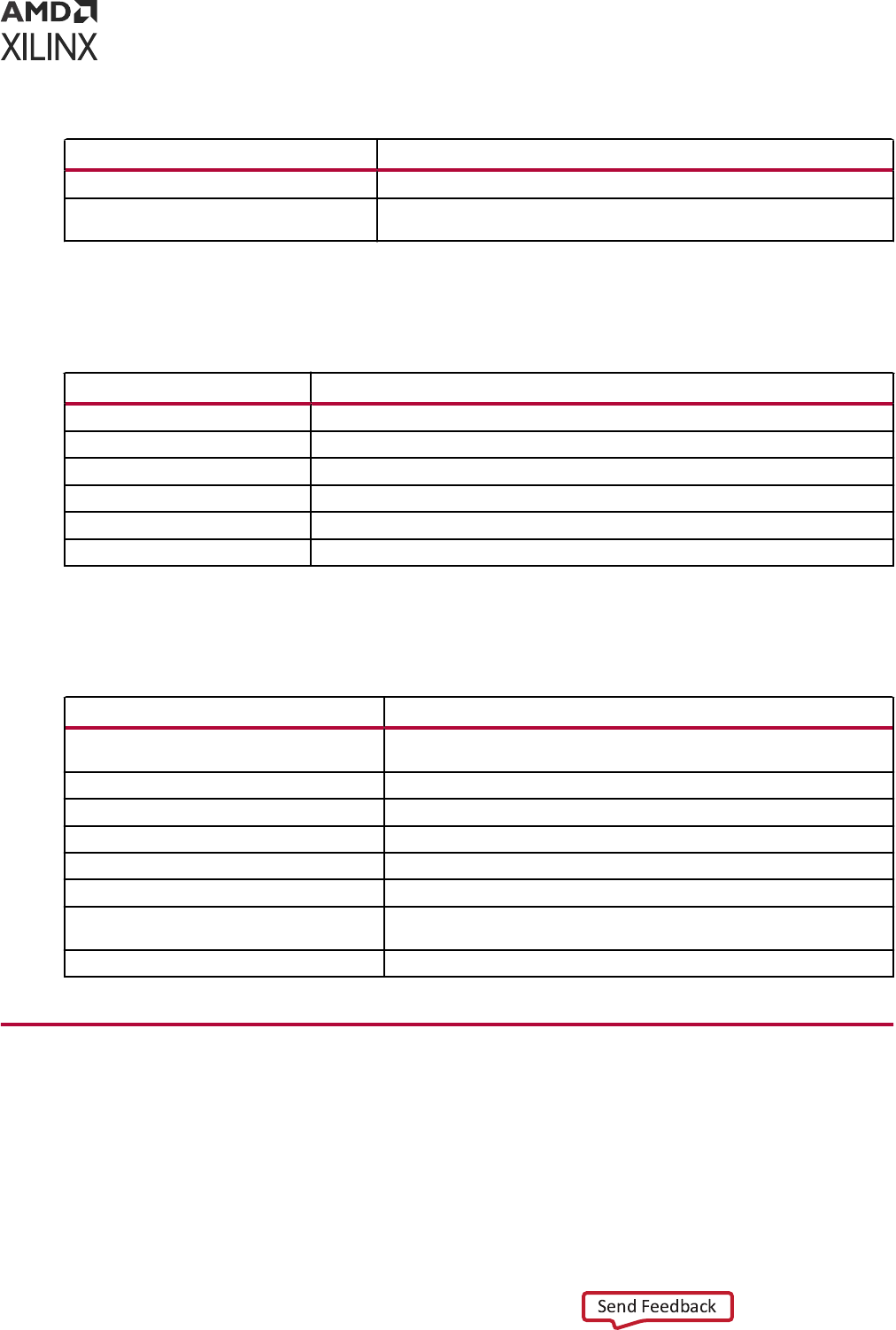
Table 33: ModelSim Simulation Options (cont'd)
Option Description
modelsim.simulate.vsim.more_option More VSIM simulation options
modelsim.simulate.custom_wave_do Name of the custom wave.do file which is used in place of a regular Vivado
generated wave.do file
VCS Simulator Simulation Options
Table 34: VCS Simulation Options
Option Description
vcs.simulate.runtime Specify simulation run time
vcs.simulate.tcl.post TCL file containing set of commands that you want to invoke at end of simulation.
vcs.simulate.log_all_signals Log all signals
vcs.simulate.saif SAIF file name
vcs.simulate.saif_scope Specify design hierarchy instance name for which power estimation is desired
vcs.simulate.vcs.more_option More VCS simulation options
Xcelium Simulator Simulation Options
Table 35: Xcelium Simulator Simulation Options
Option Description
xcelium.simulate.tcl.post TCL file containing set of commands that you want to invoke at end of
simulation
xcelium.simulate.runtime Specify simulation run time
xcelium.simulate.log_all_signals Log all signals
xcelium.simulate.update Check if unit is up-to-date before writing
xcelium.simulate.ieee_warnings Suppress IEEE warnings
xcelium.simulate.saif_scope SAIF file name
xcelium.simulate.saif Specify design hierarchy instance name for which power estimation is
desired
xcelium.simulate.xmsim.more_options More XMSIM simulation options
Netlist Options
The Netlist tab provides access to netlist conguraon opons related to SDF annotaon of the
Verilog netlist and the process corner captured by SDF delays. These opons are stored as
properes on the simulaon leset and are used while wring the netlist for simulaon.
Appendix A: Compilation, Elaboration, Simulation, Netlist, and Advanced Options
UG900 (v2022.1) April 21, 2022 www.xilinx.com
Vivado Design Suite User Guide: Logic Simulation 178
Vivado Simulator Netlist Options
Table 36: Vivado Simulator Netlist Options
Option Description
-sdf_anno
A check box is available to select the -sdf_anno option. This option is enabled by default
-process_corner
You can specify the -process_corner as fast or slow
Note: The Netlist Opons of all the third-party simulators (Questa Advanced Simulator, ModelSim
Simulator, VCS and Xcelium Simulators) are similar to the opons of Vivado simulator Netlist Opons.
Advanced Simulation Options
Advanced tab contains two opons.
• Enable incremental compilaon opon: This opon enables the incremental compilaon and
preserves the simulaon les during successive run.
• Include all design sources for simulaon opon: By default, this opon is enabled. Selecng
this opon ensures that all the les from design sources along with the les from the current
simulaon set will be used for simulaon. Even if you change the design sources, the same
changes will be updated when you launch behavioral simulaon.
IMPORTANT! This is an advanced user feature. Unchecking the box could produce unexpected results.
The Include all design sources for simulaon check box is selected by default. As long as the check box
is selected, the simulaon set includes Out-of-Context (OOC) IP, IP Integrator les, and DCP.
Unchecking the box gives you the exibility to include only the les you want to simulate, but, as
stated above, you might experience unexpected results.
Note: The Advanced Simulaon Opons are the same for all simulators.
Appendix A: Compilation, Elaboration, Simulation, Netlist, and Advanced Options
UG900 (v2022.1) April 21, 2022 www.xilinx.com
Vivado Design Suite User Guide: Logic Simulation 179

Appendix B
SystemVerilog Support in Vivado
Simulator
The Vivado simulator supports the subset of SystemVerilog. The synthesizable set of
SystemVerilog is listed in the following table. The supported test bench features are listed in
Table 38: Supported Dynamic Type Constructs.
Targeting SystemVerilog for a Specific File
By default, the Vivado IDE compiles .v les with the Verilog 2001 syntax and .sv les with the
SystemVerilog syntax.
To target SystemVerilog for a specic .v le in the Vivado IDE:
1. Right-click the le and select Set le type as shown in the gure below.
Appendix B: SystemVerilog Support in Vivado Simulator
UG900 (v2022.1) April 21, 2022 www.xilinx.com
Vivado Design Suite User Guide: Logic Simulation 180
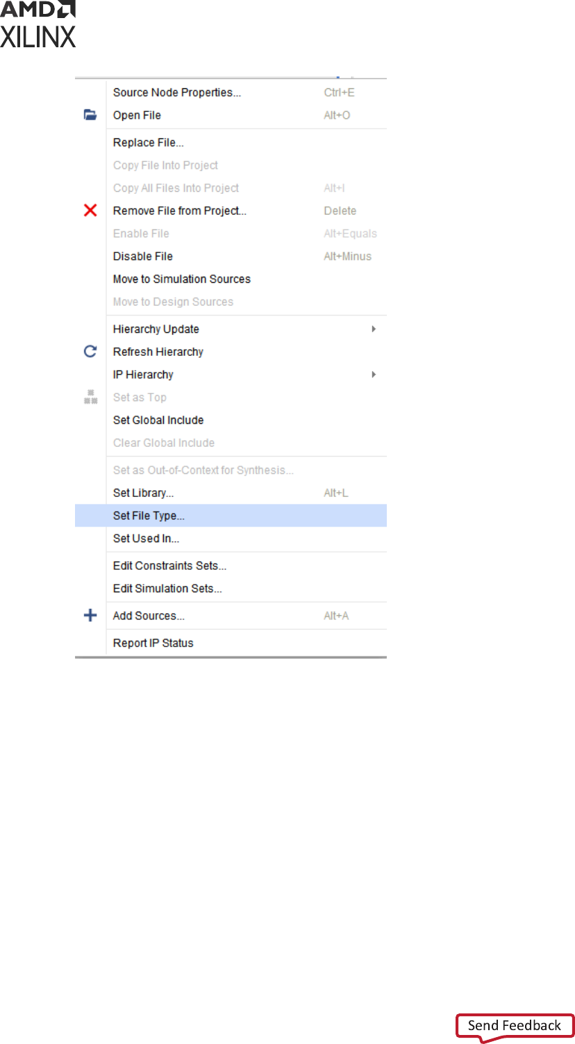
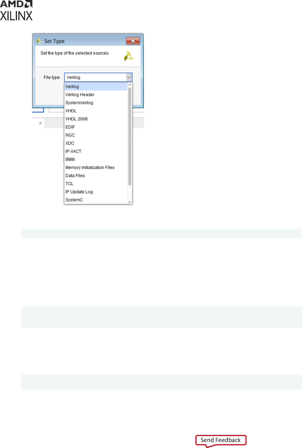
Alternavely, you can use the following command in the Tcl Console:
set_property file_type SystemVerilog [get_files <filename>.v]
Running SystemVerilog in Standalone or prj Mode
Standalone Mode
A new -sv ag has been introduced to xvlog, so if you want to read any SystemVerilog le, you
can use following command:
xvlog -sv <Design file list>
xvlog -sv -work <LibraryName> <Design File List>
xvlog -sv -f <FileName> [Where FileName contain path of test cases]
prj Mode
If you want to run the Vivado simulator in the prj-based ow, use sv as the le type, as you
would verilog or vhdl.
xvlog -prj <prj File>
xelab -prj <prj File> <topModuleName> <other options>
Appendix B: SystemVerilog Support in Vivado Simulator
UG900 (v2022.1) April 21, 2022 www.xilinx.com
Vivado Design Suite User Guide: Logic Simulation 182

Where the entry in prj le appears as follows:
verilog library1 <FileName>
sv library1 <FileName> [File parsed in SystemVerilog mode]
vhdl library2 <FileName>
sv library3 <FileName> [File parsed in SystemVerilog mode]
Table 37: Synthesizable Set of SystemVerilog 1800-2012
Primary construct Secondary construct LRM section Status
Data type 6
Singular and aggregate types 6.4 Supported
Nets and variables 6.5 Supported
Variable declarations 6.8 Supported
Vector declarations 6.9 Supported
2-state (two-value) and 4-state (four-value)
data types
6.11.2 Supported
Signed and unsigned integer types 6.11.3 Supported
Real, shortreal and realtime data types 6.12 Supported
User-defined types 6.18 Supported
Enumerations 6.19 Supported
Defining new data types as enumerated
types
6.19.1 Supported
Enumerated type ranges 6.19.2 Supported
Type checking 6.19.3 Supported
Enumerated types in numerical
expressions
6.19.4 Supported
Enumerated type methods 6.19.5 Supported
Type parameters 6.20.3 Supported
Const constants 6.20.6 Supported
Type operator 6.23 Supported
Cast operator 6.24.1 Supported
$cast dynamic casting 6.24.2 Supported
Bitstream casting 6.24.3 Supported
Aggregate data types 7
Structures 7.2 Supported
Packed/Unpacked structures 7.2.1 Supported
Assigning to structures 7.2.2 Supported
Unions 7.3 Supported
Packed/Unpacked unions 7.3.1 Supported
Tagged unions 7.3.2 Not Supported
Packed arrays 7.4.1 Supported
Unpacked arrays 7.4.2 Supported
Operations on arrays 7.4.3 Supported
Appendix B: SystemVerilog Support in Vivado Simulator
UG900 (v2022.1) April 21, 2022 www.xilinx.com
Vivado Design Suite User Guide: Logic Simulation 183

Table 37: Synthesizable Set of SystemVerilog 1800-2012 (cont'd)
Primary construct Secondary construct LRM section Status
Multidimensional arrays 7.4.5 Supported
Indexing and slicing of arrays 7.4.6 Supported
Array assignments 7.6 Supported
Arrays as arguments to subroutines 7.7 Supported
Array querying functions 7.11 Supported
Array manipulation methods 7.12 Supported
Processes 9
Combinational logic always_comb
procedure
9.2.2 Supported
Implicit always_comb sensitivities 9.2.2.1 Supported
Latched logic always_latch procedure 9.2.2.3 Supported
Sequential logic always_ff procedure 9.2.2.4 Supported
Sequential blocks 9.3.1 Supported
Parallel blocks 9.3.2 Supported
Procedural timing controls 9.4 Supported
Conditional event controls 9.4.2.3 Supported
Sequence events 9.4.2.4 Not Supported
Assignment statement 10
The continuous assignment statement 10.3.2 Supported
Variable declaration assignment (variable
initialization)
10.5 Supported
Assignment-like contexts 10.8 Supported
Array assignment patterns 10.9.1 Supported
Structure assignment patterns 10.9.2 Supported
Unpacked array concatenation 10.10 Supported
Net aliasing 10.11 Not Supported
Operators and expressions 11
Constant expressions 11.2.1 Supported
Aggregate expressions 11.2.2 Supported
Operators with real operands 11.3.1 Supported
Operations on logic (4-state) and bit (2-
state) types
11.3.4 Supported
Assignment within an expression 11.3.6 Supported
Assignment operators 11.4.1 Supported
Increment and decrement operators 11.4.2 Supported
Arithmetic expressions with unsigned and
signed types
11.4.3.1 Supported
Wildcard equality operators 11.4.6 Supported
Concatenation operators 11.4.12 Supported
Set membership operator 11.4.13 Supported
Appendix B: SystemVerilog Support in Vivado Simulator
UG900 (v2022.1) April 21, 2022 www.xilinx.com
Vivado Design Suite User Guide: Logic Simulation 184

Table 37: Synthesizable Set of SystemVerilog 1800-2012 (cont'd)
Primary construct Secondary construct LRM section Status
Concatenation of stream_expressions 11.4.14.1 Supported
Re-ordering of the generic stream 11.4.14.2 Supported
Streaming concatenation as an assignment
target (unpack)
11.4.14.3 Supported
Streaming dynamically sized data 11.4.14.4 Supported
Procedural programming
statement
12
unique-if, unique0-if and priority-
if
12.4.2 Supported
Violation reports generated by unique-if,
unique0-if, and priority-if
constructs
12.4.2.1 Supported
If statement violation reports and multiple
processes
12.4.2.2 Supported
unique-case, unique0-case, and
priority-case
12.5.3 Supported
Violation reports generated by unique-
case, unique0-case, and priority-
case construct
12.5.3.1 Supported
Case statement violation reports and
multiple processes
12.5.3.2 Supported
Set membership case statement 12.5.4 Supported
Pattern matching conditional statements 12.6 Not Supported
Loop statements 12.7 Supported
Jump statement 12.8 Supported
Tasks 13.3
Static and Automatic task 13.3.1 Supported
Tasks memory usage and concurrent
activation
13.3.2 Supported
Function 13.4
Return values and void functions 13.4.1 Supported
Static and Automatic function 13.4.2 Supported
Constant function 13.4.3 Supported
Background process spawned by function
call
13.4.4 Supported
Subroutine calls and
argument passing
13.5
Pass by value 13.5.1 Supported
Pass by reference 13.5.2 Supported
Default argument value 13.5.3 Supported
Argument binding by name 13.5.4 Supported
Optional argument list 13.5.5 Supported
Import and Export function 13.6 Supported
Appendix B: SystemVerilog Support in Vivado Simulator
UG900 (v2022.1) April 21, 2022 www.xilinx.com
Vivado Design Suite User Guide: Logic Simulation 185

Table 37: Synthesizable Set of SystemVerilog 1800-2012 (cont'd)
Primary construct Secondary construct LRM section Status
Task and function name 13.7 Supported
Utility system tasks and
system functions (only
synthesizable set)
20 Supported
I/O system tasks and
system functions (only
synthesizable set)
21 Supported
Compiler directives 22 Supported
Modules and hierarchy 23
Default port values 23.2.2.4 Supported
Top-level modules and $root 23.3.1 Supported
Module instantiation syntax 23.3.2 Supported
Nested modules 23.4 Supported
Extern modules 23.5 Supported
Hierarchical names 23.6 Supported
Member selects and hierarchical names 23.7 Supported
Upwards name referencing 23.8 Supported
Overriding module parameters 23.10 Supported
Binding auxiliary code to scopes or
instances
23.11 Not Supported
Interfaces 25
Interface syntax 25.3 Supported
Nested interface 25.3 Supported
Ports in interfaces 25.4 Supported
Example of named port bundle 25.5.1 Supported
Example of connecting port bundle 25.5.2 Supported
Example of connecting port bundle to
generic interface
25.5.3 Supported
Modport expressions 25.5.4 Supported
Clocking blocks and modports 25.5.5 Supported
Interfaces and specify blocks 25.6 Supported
Example of using tasks in interface 25.7.1 Supported
Example of using tasks in modports 25.7.2 Supported
Example of exporting tasks and functions 25.7.3 Supported
Example of multiple task exports 25.7.4 Supported
Parameterized interfaces 25.8 Supported
Virtual interfaces 25.9 Supported
Packages 26
Package declarations 26.2 Supported
Referencing data in packages 26.3 Supported
Using packages in module headers 26.4 Supported
Appendix B: SystemVerilog Support in Vivado Simulator
UG900 (v2022.1) April 21, 2022 www.xilinx.com
Vivado Design Suite User Guide: Logic Simulation 186

Table 37: Synthesizable Set of SystemVerilog 1800-2012 (cont'd)
Primary construct Secondary construct LRM section Status
Exporting imported names from packages 26.6 Supported
The std built-in package 26.7 Supported
Generate constructs 27 Supported
Testbench Feature
In Vivado simulator, support for some of the commonly used testbench features have been
added, as shown in the following table:
Table 38: Supported Dynamic Type Constructs
Primary Construct Secondary Construct LRM Section Status
String data type 6.16 Supported
String operators (table 6-9 of IEEE
1800-2012)
6.16 Supported
Len() 6.16.1 Supported
Putc() 6.16.2 Supported
Getc() 6.16.3 Supported
Toupper() 6.16.4 Supported
Tolower() 6.16.5 Supported
Compare 6.16.6 Supported
Icompare() 6.16.7 Supported
Substr() 6.16.8 Supported
Atoi(), atohex(), atooct(), atobin() 6.16.9 Supported
Atoreal() 6.16.10 Supported
Itoa() 6.16.11 Supported
Hextoa() 6.16.12 Supported
Octtoa() 6.16.13 Supported
Bintoa() 6.16.14 Supported
Realtoa() 6.16.15 Supported
Dynamic Array 7.5 Supported
Dynamic array new 7.5.1 Supported
Size 7.5.2 Supported
Delete 7.5.3 Supported
Associative Array 7.8 Supported
Wildcard index 7.8.1 Supported
String index 7.8.2 Supported
Class index 7.8.3 Supported
Appendix B: SystemVerilog Support in Vivado Simulator
UG900 (v2022.1) April 21, 2022 www.xilinx.com
Vivado Design Suite User Guide: Logic Simulation 187

Table 38: Supported Dynamic Type Constructs (cont'd)
Primary Construct Secondary Construct LRM Section Status
Integral index 7.8.4 Supported
Other user-defined types 7.8.5 Supported
Accessing invalid index 7.8.6 Supported
Associative array methods 7.9 Supported
Num() and Size() 7.9.1 Supported
Delete() 7.9.2 Supported
Exists() 7.9.3 Supported
First() 7.9.4 Supported
Last() 7.9.5 Supported
Next() 7.9.6 Supported
Prev() 7.9.7 Supported
Arguments to traversal Method 7.9.8 Supported
Associative array assignment 7.9.9 Supported
Associative array arguments 7.9.10 Supported
Associative Array literals 7.9.11 Supported
Queue 7.10 Supported
Queue operators 7.10.1 Supported
Queue methods 7.10.2 Supported
Size() 7.10.2.1 Supported
Insert() 7.10.2.2 Supported
Delete() 7.10.2.3 Supported
Pop_front() 7.10.2.4 Supported
Pop_back() 7.10.2.5 Supported
Push_front() 7.10.2.6 Supported
Push_back() 7.10.2.7 Supported
Persistence of references to
elements of a queue
7.10.3 Supported
Updating a queue using
assignment and unpacked array
concatenation
7.10.4 Supported
Bounded queues 7.10.5 Supported
Class 8 Supported
Class General 8.1 Supported
Overviews 8.2 Supported
Syntax 8.3 Supported
Objects(Class instance) 8.4 Supported
Object properties and object
parameter data
8.5 Supported
Object methods 8.6 Supported
Constructors 8.7 Supported
Appendix B: SystemVerilog Support in Vivado Simulator
UG900 (v2022.1) April 21, 2022 www.xilinx.com
Vivado Design Suite User Guide: Logic Simulation 188

Table 38: Supported Dynamic Type Constructs (cont'd)
Primary Construct Secondary Construct LRM Section Status
Static class properties 8.8 Supported
Static methods 8.9 Supported
This 8.10 Supported
Assignment, renaming, and
copying
8.11 Supported
Inheritance and subclasses 8.12 Supported
Overridden members 8.13 Supported
Super 8.14 Supported
Casting 8.15 Supported
Chaining constructors 8.16 Supported
Data hiding and encapsulation 8.17 Supported
Constant class properties 8.18 Supported
Virtual methods 8.19 Supported
Abstract classes and pure virtual
methods
8.20 Supported
Polymorphism: dynamic method
lookup
8.21 Supported
Class scope resolution operator :: 8.22 Supported
Out-of-block declarations 8.23 Supported
Parameterized classes 8.24 Supported
Class resolution operator for
parameterized classes
8.24.1 Supported
Typedef class 8.25 Supported
Interface classes 8.26 Supported
Multiple inheritance of Interface
classes
8.26.6 Supported
Memory management 8.27 Supported
Classes and structures 8.28 Supported
Processes 9 Supported
Parallel Process - Fork Join_Any
and Fork Join_None
9.3 Supported
Wait fork 9.6.1 Supported
Disable Fork 9.6.3 Supported
Fine grain process control 9.7 Supported
Clocking Block 14 Supported
General 14.1 Supported
Overview 14.2 Supported
Clocking block declaration 14.3 Supported
Input and output Skew 14.4 Supported
Hierarchical Expressions 14.5 Not Supported
Signals in multiple clocking block 14.6 Supported
Appendix B: SystemVerilog Support in Vivado Simulator
UG900 (v2022.1) April 21, 2022 www.xilinx.com
Vivado Design Suite User Guide: Logic Simulation 189

Table 38: Supported Dynamic Type Constructs (cont'd)
Primary Construct Secondary Construct LRM Section Status
Clocking block scope and lifetime 14.7 Supported
Multiple clocking block example 14.8 Supported
Interface and clocking block 14.9 Supported
Clocking block event 14.10 Supported
Cycle Delay 14.11 Supported
Default clocking 14.12 Supported
Input Sampling 14.13 Supported
Global clocking 14.14 Not Supported
Synchronous events 14.15 Supported
Synchronous drives 14.16 Supported
Drives and nonblocking
assignments
14.16.1 Supported
Driving clocking output signals 14.16.2 Supported
Semaphore 15.3 Supported
Semaphore method new() 15.3.1 Supported
Semaphore method put() 15.3.2 Supported
Semaphore method get() 15.3.3 Supported
Semaphore method try_get() 15.3.4 Supported
Mailbox 15.4 Supported
Mailbox method new() 15.4.1 Supported
Mailbox method num() 15.4.2 Supported
Mailbox method put() 15.4.3 Supported
Mailbox method try_put() 15.4.4 Supported
Mailbox method get() 15.4.5 Supported
Mailbox method try_get() 15.4.6 Supported
Mailbox method peek() 15.4.7 Supported
Mailbox method try_peek() 15.4.8 Supported
Parameterized mailbox 15.4.9 Supported
Named Event 15.5 Supported
Triggering an event 15.5.1 Supported
Waiting on event 15.5.2 Supported
Persistent trigger 15.5.3 Not Supported
Event Sequence 15.5.4 Not Supported
Operation on named event
variable
15.5.5 Supported
Merging Events 15.5.5.1 Supported
Reclaiming event 15.5.5.2 Supported
Event comparison 15.5.5.3 Supported
Assertion 16 Supported
General 16.1 Supported
Appendix B: SystemVerilog Support in Vivado Simulator
UG900 (v2022.1) April 21, 2022 www.xilinx.com
Vivado Design Suite User Guide: Logic Simulation 190

Table 38: Supported Dynamic Type Constructs (cont'd)
Primary Construct Secondary Construct LRM Section Status
Overview 16.2 Supported
Assert 16.2 Supported
Assume 16.2 Supported
Cover 16.2 Not Supported
Restrict 16.2 Not Supported
Immediate assertion 16.3 Supported
Deferred assertion 16.4 Not Supported
Concurrent assertion overview 16.5 Supported
Sampling 16.5.1 Supported
Assertion clock 16.5.2 Supported
Boolean expression 16.6 Supported
Sequence 16.7 Supported
Declaring sequence 16.8 Supported
Typed formal argument in
sequence declarations
16.8.1 Supported
Local variable formal arguments
in sequence declarations
16.8.2 Supported
Sequence operations 16.9 Supported
Operator precedence 16.9.1 Supported
Repetition in sequences 16.9.2 Supported
Sampled value functions 16.9.3 Supported
Global clocking past and future
sampled value functions
16.9.4 Not Supported
AND operation 16.9.5 Supported
Intersection (AND with length
restriction)
16.9.6 Supported
OR operation 16.9.7 Supported
First_match operation 16.9.8 Supported
Conditions over sequences 16.9.9 Supported
Sequence contained within
another sequence
16.9.10 Supported
Composing sequences from
simpler subsequences
16.9.11 Supported
Local variables 16.10 Supported
Calling subroutines on match of a
sequence
16.11 Supported
Declaring properties 16.12 Supported
Sequence property 16.12.1 Supported
Negation property 16.12.2 Supported
Disjunction property 16.12.3 Supported
Conjunction property 16.12.4 Supported
Appendix B: SystemVerilog Support in Vivado Simulator
UG900 (v2022.1) April 21, 2022 www.xilinx.com
Vivado Design Suite User Guide: Logic Simulation 191

Table 38: Supported Dynamic Type Constructs (cont'd)
Primary Construct Secondary Construct LRM Section Status
If-else property 16.12.5 Supported
Implication 16.12.6 Supported
Implies and iff properties 16.12.7 Supported
Property instantiation 16.12.8 Supported
Followed-by property 16.12.9 Not Supported
Next time property 16.12.10 Not Supported
Always property 16.12.11 Not Supported
Until property 16.12.12 Not Supported
Eventually property 16.12.13 Not Supported
Abort properties 16.12.14 Not Supported
Weak and strong operators 16.12.15 Not Supported
Case 16.12.16 Not Supported
Recursive properties 16.12.17 Not Supported
Typed formal arguments in
property declarations
16.12.18 Supported
Local variable formal arguments
in property declarations
16.12.19 Supported
Property examples 16.12.20 Supported
Finite-length versus infinite-length
behavior
16.12.21 Supported
Nondegeneracy 16.12.22 Supported
Multiclock support 16.13 Not Supported
Concurrent assertions 16.14 Supported
Assert statement 16.14.1 Supported
Assume statement 16.14.2 Supported
Cover statement 16.14.3 Not Supported
Restrict statement 16.14.4 Not Supported
Using concurrent assertion
statements outside procedural
code
16.14.5 Supported
Embedding concurrent assertions
in procedural code
16.14.6 Not Supported
Inferred value functions 16.14.7 Not Supported
Nonvacuous evaluations 16.14.8 Not Supported
Disable iff resolution 16.15 Supported
Clock resolution 16.16 Supported
Semantic leading clocks for
multiclocked sequence and
properties
16.16.1 Supported
Expect statement 16.17 Not Supported
Clocking blocks and concurrent
assertions
16.18 Supported
Appendix B: SystemVerilog Support in Vivado Simulator
UG900 (v2022.1) April 21, 2022 www.xilinx.com
Vivado Design Suite User Guide: Logic Simulation 192

Table 38: Supported Dynamic Type Constructs (cont'd)
Primary Construct Secondary Construct LRM Section Status
Random Constraint 18 Supported
Concepts and Usage 18.3 Supported
Random Variable 18.4 Supported
Rand modifier 18.4.1 Supported
Randc modifier 18.4.2 Supported
Constraint block 18.5 Supported
External constraint block 18.5.1 Supported
Constraint inheritance 18.5.2 Supported
Set membership 18.5.3 Supported
Distribution 18.5.4 Supported
Implication 18.5.6 Supported
If-else constraint 18.5.7 Supported
Iterative constraint 18.5.8 Supported
foreach iterative constraint 18.5.8.1 Supported
Array reduction iterative
constraint
18.5.8.2 Supported
Global constraint 18.5.9 Supported
Variable Ordering 18.5.10 Supported
Static constraint block 18.5.11 Supported
Function in constraint 18.5.12 Supported
Constraint Guards 18.5.13 Supported
Soft constraint 18.5.14 Supported
Method Randomize 18.6.1 Supported
Pre_randomize and
post_randomize
18.6.2 Supported
Behavior of randomization
method
18.6.3 Supported
In-line constraints 18.7 Supported
Local scope resolution 18.7.1 Supported
Disabling random variable with
rand_mode
18.8 Supported
Controlling constraints with
constraint_mode
18.9 Supported
Dynamic constraint modification 18.10 Supported
In-line random variable control 18.11 Supported
In-line constraint checker 18.11.1 Supported
Randomize of a scope variable
std::randomize
18.12 Supported
Adding constraint to scope
variables std::randomize with
18.12.1 Supported
Random number system
functions and method
18.13 Supported
Appendix B: SystemVerilog Support in Vivado Simulator
UG900 (v2022.1) April 21, 2022 www.xilinx.com
Vivado Design Suite User Guide: Logic Simulation 193

Table 38: Supported Dynamic Type Constructs (cont'd)
Primary Construct Secondary Construct LRM Section Status
$urandom 18.13.1 Supported
$urandom_range 18.13.2 Supported
srandom 18.13.3 Supported
Get_randstate 18.13.4 Supported
Set_randstate 18.13.5 Supported
Random stability 18.14 Supported
Manually seeding randomization 18.15 Supported
Randcase 18.16 Supported
Randsequence 18.17 Not Supported
Programs 24 Supported
The Program construct 24.3 Supported
Scheduling semantic of code in
program construct
24.3.1 Supported
Program port connection 24.3.2 Supported
Eliminating test bench race 24.4 Supported
Blocking task in cycle/event mode 24.5 Supported
Anonymous Programs 24.6 Not Supported
Program control task 24.7 Supported
Functional Coverage 19 Supported
General 19.1 Supported
Overview 19.2 Supported
Defining coverage model:
covergroup
19.3 Supported
Using covergroup in classes 19.4 Supported
Defining coverage points 19.5 Supported
Specifying bins for values 19.5.1 Supported
Coverpoint bin with covergroup
expressions
19.5.1.1 Supported
Coverpoint bin set covergroup
expressions
19.5.1.2 Not supported
Specifying bins for transitions 19.5.2 Supported
Automatic bin creation for
coverage points
19.5.3 Supported
Wildcard specification of coverage
point bins
19.5.4 Supported
Excluding coverage point values
or transitions
19.5.5 Supported
Specifying Illegal coverage point
values or transitions
19.5.6 Supported
Value resolution 19.5.7 Supported
Defining cross coverage 19.6 Supported
Defining cross coverage bins 19.6.1 Supported
Appendix B: SystemVerilog Support in Vivado Simulator
UG900 (v2022.1) April 21, 2022 www.xilinx.com
Vivado Design Suite User Guide: Logic Simulation 194
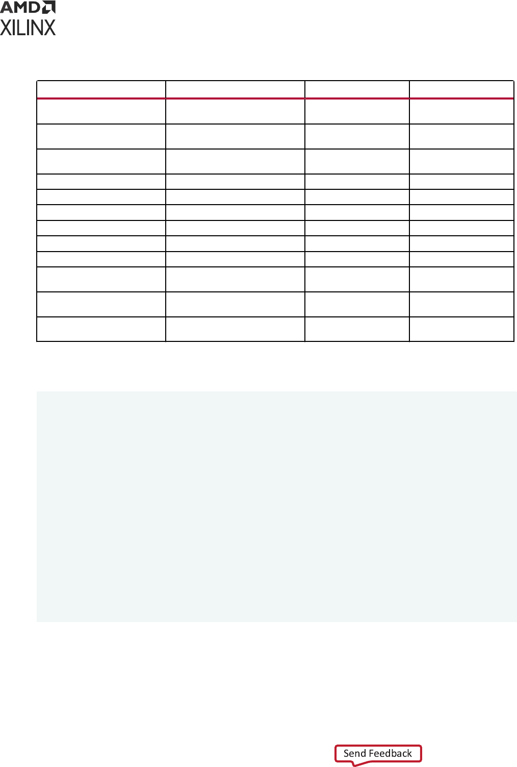
Table 38: Supported Dynamic Type Constructs (cont'd)
Primary Construct Secondary Construct LRM Section Status
Example of user-defined cross
coverage and select expressions
19.6.1.1 Supported
Cross bin with covergroup
expressions
19.6.1.2 Supported
Cross bin automatically defined
types
19.6.1.3 Supported
Cross bin set expression 19.6.1.4 Supported
Excluding cross products 19.6.2 Supported
Specifying illegal cross products 19.6.3 Supported
Specifying coverage options 19.7 Supported
Covergroup type options 19.7.1 Supported
Predefined coverage methods 19.8 Supported
Overriding the built-in sample
method
19.8.1 Supported
Predefined coverage system tasks
and system functions
19.9 Supported
Organization of option and
type_option members
19.10 Supported
Note: Sensivity on dynamic types such as Queue, Dynamic Array, Associave Array, and Class are not
supported, therefore, block waing on dynamic type update may not work correctly. For example:
module top();
int c[$];
event e1;
initial
begin
c[0] = 10;
for(int i = 0; i <= 10; i++)
begin
c = {i, c};
-> e1;
#5;
end
end
always@(*) $display($time, " trying to read sensitivity on dynamic type :
%d", c[0]);
// this won't work as sensitivity on dynamic type is not supported
always @(e1) $display($time, " coming from event sensitivity : %d",
c[0]); // this we
can do as WA
always_comb if(c.size() > 0) $display($time, " Coming from size
sensitivity : %d",
c[0]); // sensitivity on size works
Appendix B: SystemVerilog Support in Vivado Simulator
UG900 (v2022.1) April 21, 2022 www.xilinx.com
Vivado Design Suite User Guide: Logic Simulation 195

Appendix C
Universal Verification Methodology
Support
Vivado
®
integrated design environment supports universal vericaon methodology (UVM) in
Vivado simulator (XSim). The UVM version 1.2 library is precompiled and is available with Vivado.
If you are running your design through Vivado, you need not set anything. But if you are running
standalone Vivado simulator, then you need to pass -L uvm to xvlog and xelab command.
By default, Vivado simulator supports UVM version 1.2. If you want to use UVM version 1.1, you
need to pass -uvm_version 1.1 to xvlog and xelab command. Set the following properes
if you are using it through the Vivado integrated design environment:
set_property -name {xsim.compile.xvlog.more_options} -value {-uvm_version
1.1} -objects [get_filesets sim_1]
set_property -name {xsim.elaborate.xelab.more_options} -value {-uvm_version
1.1} -objects [get_filesets sim_1]
You can also set these properes from Vivado GUI using Compilaon and Elaboraon tab in
simulaon sengs. For more informaon, see Using Simulaon Sengs.
Appendix C: Universal Verification Methodology Support
UG900 (v2022.1) April 21, 2022 www.xilinx.com
Vivado Design Suite User Guide: Logic Simulation 196

Appendix D
VHDL 2008 Support in Vivado
Simulator
Introduction
The Vivado
®
simulator supports the subset of VHDL 2008 (IEEE 1076-2008). The complete list
is given in Supported features of VHDL 2008 (IEEE1076-2008).
Compiling and Simulating
The Vivado simulator executable xvhdl is used to convert a VHDL design unit into parser dump
(.vdb). By default, Vivado simulator uses mixed 93 and 2008 standard (STD) and IEEE packages
to freely allow mixing of 93 and 2008 features. If you want to force only the VHDL-93 standard
(STD) and IEEE package, pass -93_mode to xvhdl. To compile a le only with VHDL 2008 mode,
you need to pass -2008 switch to xvhdl.
For example, to compile a design called top.vhdl in VHDL-2008, following command line can be
used:
xvhdl -2008 -work mywork top.vhdl
The Vivado simulator executable xelab is used to elaborate a design and produce an executable
image for simulaon.
xelab can do either of the following:
• Elaborate on parser dumps produced by xvhdl
• Directly use vhdl source les.
No switch is needed to elaborate on parser dumps produced by xvhdl. You can pass -vhdl2008
to xelab to directly use vhdl source les.
Appendix D: VHDL 2008 Support in Vivado Simulator
UG900 (v2022.1) April 21, 2022 www.xilinx.com
Vivado Design Suite User Guide: Logic Simulation 197

Example 1:
xelab top -s mysim; xsim mysim -R
Example 2:
xelab -vhdl2008 top.vhdl top -s mysim; xsim mysim -R
Instead of specifying VHDL les in the command line for xvhdl and xelab, a .prj le can be
used. If you have two les for a design called top.vhdl (2008 mode) and bot.vhdl (93 mode),
you can create a project le named example.prj as follows:
vhdl xil_defaultlib bot.vhdl
vhdl2008 xil_defaultlib top.vhdl
In the project le, each line starts with the language type of the le, followed by the library name
such as xil_defaultlib and one or more le names with a space separator. For VHDL 93,
one should use vhdl as the language type. For VHDL 2008, use vhdl2008 instead.
A .prj le can be used as shown in the example below:
xelab -prj example.prj xil_defaultlib.top -s mysim; xsim mysim -R
Alternavely, to mix VHDL 93 and VHDL 2008 design units, compile the les separately with a
proper language mode specied to xvhdl. Then, elaborate on top(s) of the design. For example,
if we have a VHDL 93 module called bot in le bot.vhdl, and a VHDL-2008 module called top
in le top.vhdl, you can compile them as shown in the example below:
xvhdl bot.vhdl
xvhdl -2008 top.vhdl
xelab -debug typical top -s mysim
Once the executable is produced by xelab, you can run the simulaon as usual.
Example 1:
xsim mysim -gui
Example 2:
xsim mysim -R
Appendix D: VHDL 2008 Support in Vivado Simulator
UG900 (v2022.1) April 21, 2022 www.xilinx.com
Vivado Design Suite User Guide: Logic Simulation 198

Fixed and Floating Point Packages
Fixed and oang point packages used by the Vivado simulator are the new enhanced IEEE
standard packages introduced in VHDL-2008. If you are using the VHDL-93 standard xed or
oang package, that may work in Vivado synthesis, however you must edit your VHDL source
le for simulaon.
For example, if you are using the following syntax for the xed package in Vivado synthesis:
library ieee;
use ieee.fixed_pkg.all;
Change this to the following syntax in VHDL-2008 for use in the Vivado simulator:
library ieee_proposed;
use ieee_proposed.fixed_pkg.all;
See this link in the Vivado Design Suite User Guide: Synthesis (UG901) for more informaon about
xed and oang packages in Vivado Synthesis.
Similar changes will apply for oang package too.
Supported Features
Following are the supported features of VHDL 2008 (IEEE1076-2008):
• Matching relaonal operators.
• Maximum and minimum operators.
• Shi operators (rol, ror, sll, srl, sla, and sra).
• Unary logical reducon operators.
• Mixing array and scalar logical operators.
• If-else-if and case generate.
• Sequenal assignments.
• Case? Statements.
• Select? Statements.
• Unconstrained element types.
• boolean_vector and integer_vector array types.
• Reading output ports.
• Expressions in port maps.
Appendix D: VHDL 2008 Support in Vivado Simulator
UG900 (v2022.1) April 21, 2022 www.xilinx.com
Vivado Design Suite User Guide: Logic Simulation 199

• Process (all) statement.
• Referencing generics in generic lists.
• Generic types in enes.
• Relaxed return rules for funcon return values.
• Extensions to globally stac and locally stac expressions.
• Stac ranges and integer expressions in range bounds.
• Block comments.
• Context declaraon.
• Array slices in aggregate.
• Protected types.
• External name to signal.
Note: For detailed informaon about features, see Supported VHDL-2008 Features secon in Vivado
Design Suite User Guide: Synthesis (UG901).
Appendix D: VHDL 2008 Support in Vivado Simulator
UG900 (v2022.1) April 21, 2022 www.xilinx.com
Vivado Design Suite User Guide: Logic Simulation 200

Appendix E
Direct Programming Interface (DPI)
in Vivado Simulator
Introduction
You can use the SystemVerilog Direct Programming Interface (DPI) to bind C code to
SystemVerilog code. Using DPI, SystemVerilog code can call a C funcon, which in turn can call
back a SystemVerilog task or funcon. Vivado
®
simulator supports all the constructs as DPI task/
funcon, as described below.
Compiling C Code
A new compiler executable, xsc, is provided to convert C code into an object code le and to
link mulple object code les into a shared library (.a on Windows and .so on Linux). The xsc
compiler is available in the <Vivado installation>/bin directory. You can use -sv_lib to
pass the shared library containing your C code to the Vivado simulator/elaborator executable.
The xsc compiler works in the same way as a C compiler, such as gcc. The xsc compiler:
• Calls the LLVM clang compiler to convert C code into object code
• Calls the GNU linker to create a shared library (.a on Windows and .so on Linux) from one or
more object les corresponding to the C les
The shared library generated by the xsc compiler is linked with the Vivado simulator kernel using
one or more newly added switches in xelab, as described below. The simulaon snapshot created
by xelab thus has ability to connect the compiled C code with compiled SystemVerilog code and
eect communicaon between C and SystemVerilog.
Appendix E: Direct Programming Interface (DPI) in Vivado Simulator
UG900 (v2022.1) April 21, 2022 www.xilinx.com
Vivado Design Suite User Guide: Logic Simulation 201
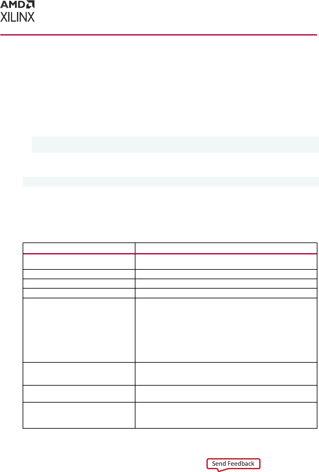
xsc Compiler
The xsc compiler helps you to create a shared library (.a on Windows or .so on Linux) from one
or more C les. Use xelab to bind the shared library generated by xsc into the rest of your design.
You can create a shared library using the following processes:
• One-step process: Pass all C les to xsc without using the -compile or -shared/
shared_systemc/static switch.
• Two-step process:
xsc -compile <C files>
xsc --shared or -shared_systemc or -static <object files>
Usage
xsc [options] <files...>
Switches
You can use a double dash (--) or a single dash (-) for switches.
Table 39: XSC Compiler Switches
Switch Description
-compile [c]
Generate the object files only from the source C files. The link stage is not
run.
-f [ -file ] <arg>
Read additional options from the specified file.
-h [ -help ]
Print this help message.
-i [ -input_file ] <arg>
List of input files (one file per switch) for compiling or linking.
-mt <arg> (=auto)
Specifies the number of sub-compilation jobs that can be run in parallel.
Choices are:
• auto: automatic
• n: where n is an integer greater than 1
• off: turn off multi-threading
Default: auto
-o [ -output ] <arg>
Specify the name of output shared library. Works with --shared, --
shared_systemc, --exe options only. Default for shared library is
<current_directory>/xsim.dir/work/xsc/dpi.so.
-work <arg>
Specify the work directory in which to place the outputs (object files).
Default: <current_directory>/xsim.dir/xsc
-v [ -verbose ] <arg>
Specify verbosity level for printing messages.
Allowed values are: 0, 1
Default: 0
Appendix E: Direct Programming Interface (DPI) in Vivado Simulator
UG900 (v2022.1) April 21, 2022 www.xilinx.com
Vivado Design Suite User Guide: Logic Simulation 202

Table 39: XSC Compiler Switches (cont'd)
Switch Description
-gcc_compile_options <arg>
Supply an additional option to the compiler. You can use multiple -
gcc_compile_options switches.
-gcc_link_options <arg>
Supply an additional option to the linker. You can use multiple -
gcc_link_options switches.
-shared
Run only the linking stage to generate the shared library (.so) from the
object files.
-gcc_version
Print version of the C compiler used internally.
-gcc_path
Print path of the C compiler used internally.
-lib <arg>
Specify the logical library directories that will be read. Default is
<current_directory>/xsim.dir/xs.
-cppversion <arg>
Set the CPP version. Currently CPP 11 and 14 are supported. Default is 11.
--shared_systemc
Run only the linking stage to generate the shared library (.dll) for SystemC
from the object files.
--static
Run only the linking stage to generate a static library (.a) for SystemC from
the object files.
--exe
Create executable for standalone SystemC.
--version
Print version of the Vivado Simulator xsc being used.
--debug
Debug SystemC modules. This option is relevant only when used together
with -exe option, otherwise is ignored.
--print_gcc_version
Print version of the C compiler used internally
Examples
xsc function1.c function2.c
xelab -svlog file.sv -sv_lib dpi
xsc -compile function1.c function2.c -work abc
xsc -shared abc/function1.lnx64.o abc/function2.lnx64.o -work abc
Note: By default, Linux uses the LD_LIBRARY_PATH for searching the DPI libraries. Hence, provide -
dpi_absolute ag to xelab on Linux if library name start with lib*.
Note: You can use -additional_option to the compiler to pass extra switch.
• Example:
xsc t1.c --additional_option "-I<path>"
• Example to pass mulple path:
xsc t1.c --additional_option "-I<path>" --additional_option "-I<path>"
Appendix E: Direct Programming Interface (DPI) in Vivado Simulator
UG900 (v2022.1) April 21, 2022 www.xilinx.com
Vivado Design Suite User Guide: Logic Simulation 203
Binding Compiled C Code to SystemVerilog
Using xelab
The DPI-related switches for xelab that bind the compiled C code to SystemVerilog are as
follows:
Table 40: DPI-Related Switches for xelab
Switch Description
-sv_root arg
Root directory relative to which a DPI shared library should be searched. (Default:
<current_directory>/xsim.dir/xsc)
-sv_lib arg
Name of the DPI shared library without the file extension defining C function imported in
SystemVerilog.
-sv_liblist arg
Bootstrap file pointing to DPI shared libraries.
-dpiheader arg
Generate a DPI C header file containing C declaration of imported and exported functions.
-dpi_absolute Use absolute paths instead of LD_LIBRARY_PATH on Linux for DPI libraries that are formatted as
lib<libname>.so.
-dpi_stacksize arg User defined stack size for DPI tasks.
For more informaon on r-sv_liblist arg, refer to the IEEE Standard for SystemVerilog—
Unied Hardware Design, Specicaon, and Vericaon Language, Appendix J.4.1, page 1228.
Data Types Allowed on the Boundary of C and
SystemVerilog
The IEEE Standard for SystemVerilog allows only subsets of C and SystemVerilog data types on
the C and SystemVerilog boundary. Provided below are (1) details on data types supported in
Vivado simulator and (2) descripons of mapping between the C and SystemVerilog data types.
Supported Data Types
The following table describes data types allowed on the boundary of C and SystemVerilog, along
with mapping of data types from SystemVerilog to C and vice versa.
Table 41:
Data Types Allowed on the C-SystemVerilog Boundary
SystemVerilog C Supported Comments
byte char
Yes None
shortint short int
Yes None
Appendix E: Direct Programming Interface (DPI) in Vivado Simulator
UG900 (v2022.1) April 21, 2022 www.xilinx.com
Vivado Design Suite User Guide: Logic Simulation 204

Table 41: Data Types Allowed on the C-SystemVerilog Boundary (cont'd)
SystemVerilog C Supported Comments
int int
Yes None
longint long long
Yes None
real double
Yes None
shortreal float
Yes None
chandle void *
Yes None
string const char*
Yes None
bit unsigned char
Yes sv_0, sv_1
Available on C side using svdpi.h
logic, reg
unsigned char
Yes sv_0, sv_1, sv_z, sv_x:
Array (packed) of bits
svBitVecVal
Yes Defined in svdpi.h
Array (packed) of logic/reg
svLogicVecVal
Yes Defined in svdpi.h
enum
Underlying enum type Yes None
Packed struct, union Passed as array Yes None
Unpacked arrays of bit, logic Passed as array Yes C can call SystemVerilog
Unpacked struct Passed as struct Yes None
Unpacked union Passed as struct No None
Open arrays
svOpenArrayHandle
Yes None
To generate a C header le that provides details on how SystemVerilog data types are mapped to
C data types: pass the parameter -dpiheader <file name> to xelab. Addional details on
data type mapping are available in the The IEEE Standard for SystemVerilog.
Mapping for User-Defined Types
Enum
You can dene an enumerated type (enum) for conversion to the equivalent SystemVerilog types,
svLogicVecVal or svBitVecVal, depending on the base type of enum. For enumerated
arrays, equivalent SystemVerilog arrays are created.
Appendix E: Direct Programming Interface (DPI) in Vivado Simulator
UG900 (v2022.1) April 21, 2022 www.xilinx.com
Vivado Design Suite User Guide: Logic Simulation 205
Examples
• SystemVerilog types::
typedef enum reg [3:0] { a = 0, b = 1, c} eType;
eType e;
eType e1[4:3];
typedef enum bit { a = 0, b = 1} eTypeBit;
eTypeBit e3;
eTypeBit e4[3:1] ;
• C types:
svLogicVecVal e[SV_PACKED_DATA_NELEMS(4)];
svLogicVecVal e1[2][SV_PACKED_DATA_NELEMS(4)];
svBit e3;
svBit e4[3];
TIP: The C argument types depend on the base type of the
enum
and the direcon.
Packed Struct/Union
When using a packed struct or union type, an equivalent SystemVerilog type, svLogicVecVal
or svBitVecVal, is created on the DPI C side.
Examples
• SystemVerilog type:
typedef struct packed {
int i;
bit b;
reg [3:0]r;
logic [2:0] [4:8][9:1] l;
} sType;
sType c_obj;
sType [3:2] c_obj1[5];
• C type:
svLogicVecVal c_obj[SV_PACKED_DATA_NELEMS(172)];
svLogicVecVal c_obj1[5][SV_PACKED_DATA_NELEMS(344)];
Arrays, both packed and unpacked, are represented as arrays of svLogicVecVal or
svBitVecVal.
Unpacked Struct
An equivalent unpacked type is created on the C side, in which all the members are converted to
the equivalent C representaon.
Appendix E: Direct Programming Interface (DPI) in Vivado Simulator
UG900 (v2022.1) April 21, 2022 www.xilinx.com
Vivado Design Suite User Guide: Logic Simulation 206

Examples
• SystemVerilog type:
typedef struct {
int i;
bit b;
reg r[3:0];
logic [2:0] l[4:8][9:1];
} sType;
• C type:
typedef struct {
int i;
svBit b;
svLogic r[4];
svLogicVecVal l[5][9][SV_PACKED_DATA_NELEMS(3)];
} sType;
Support for svdpi.h Functions
The svdpi.h header le is provided in this directory: <vivado installation>/data/
xsim/include.
The following svdpi.h funcons are supported:
svBit svGetBitselBit(const svBitVecVal* s, int i);
svLogic svGetBitselLogic(const svLogicVecVal* s, int i);
void svPutBitselBit(svBitVecVal* d, int i, svBit s);
void svPutBitselLogic(svLogicVecVal* d, int i, svLogic s);
void svGetPartselBit(svBitVecVal* d, const svBitVecVal* s, int i, int w);
void svGetPartselLogic(svLogicVecVal* d, const svLogicVecVal* s, int i, int
w);
void svPutPartselBit(svBitVecVal* d, const svBitVecVal s, int i, int w);
void svPutPartselLogic(svLogicVecVal* d, const svLogicVecVal s, int i, int
w);
const char* svDpiVersion();
svScope svGetScope();
svScope svSetScope(const svScope scope);
const char* svGetNameFromScope(const svScope);
int svPutUserData(const svScope scope, void*userKey, void* userData);
void* svGetUserData(const svScope scope, void* userKey);
Appendix E: Direct Programming Interface (DPI) in Vivado Simulator
UG900 (v2022.1) April 21, 2022 www.xilinx.com
Vivado Design Suite User Guide: Logic Simulation 207

Open Arrays in DPI
When declaring an import funcon in SystemVerilog, you may specify formal argument as open
arrays. By specifying certain dimension(s) of formal array arguments as blank (open), it will allow
passing actual arguments of dierent size, which facilitates more general C code. At C side, the
open arrays are represented as SVOpenArrayHandle. By passing this handle to provided
funcons, you may query the informaon of open array, e.g. the size of opened dimension, and
access the actual data.
Declaration
Open arrays may only appear in import funcon/task declaraon in SystemVerilog code. By
leaving the dimension(s) open, you must specify an open array and the size of blank dimension
will be determined with respect to actual argument.
Examples
SystemVerilog funcon declaraon:
import "DPI-C" function int myFunction1(input bit[] v);
import "DPI-C" function void myFunction2(input int v1[], input int v2[],
output int
v3[]);
At C side, the open array(s) may only be accessed by the handle and provided APIs:
int myFunction1(const SVOpenArrayHandle v);
void myFunction2(const SVOpenArrayHandle v1, const SVOpenArrayHandle v2,
const
SVOpenArrayHandle v3);
svdpi.h Support
The following open array related funcons are supported in svdpi.h:
int svLeft(const svOpenArrayHandle h, int d);
int svRight(const svOpenArrayHandle h, int d);
int svLow(const svOpenArrayHandle h, int d);
int svHigh(const svOpenArrayHandle h, int d);
int svIncrement(const svOpenArrayHandle h, int d);
int svSize(const svOpenArrayHandle h, int d);
int svDimensions(const svOpenArrayHandle h);
void *svGetArrayPtr(const svOpenArrayHandle);
int svSizeOfArray(const svOpenArrayHandle);
void *svGetArrElemPtr(const svOpenArrayHandle, int indx1, ...);
void *svGetArrElemPtr1(const svOpenArrayHandle, int indx1);
void *svGetArrElemPtr2(const svOpenArrayHandle, int indx1, int indx2);
void *svGetArrElemPtr3(const svOpenArrayHandle, int indx1, int indx2,
int indx3);
void svPutBitArrElemVecVal(const svOpenArrayHandle d, const svBitVecVal* s,
int indx1, ...);
void svPutBitArrElem1VecVal(const svOpenArrayHandle d, const svBitVecVal* s,
int indx1);
Appendix E: Direct Programming Interface (DPI) in Vivado Simulator
UG900 (v2022.1) April 21, 2022 www.xilinx.com
Vivado Design Suite User Guide: Logic Simulation 208

void svPutBitArrElem2VecVal(const svOpenArrayHandle d, const svBitVecVal* s,
int indx1, int indx2);
void svPutBitArrElem3VecVal(const svOpenArrayHandle d, const svBitVecVal* s,
int indx1, int indx2, int indx3);
void svPutLogicArrElemVecVal(const svOpenArrayHandle d, const svLogicVecVal*
s, int indx1, ...);
void svPutLogicArrElem1VecVal(const svOpenArrayHandle d, const
svLogicVecVal*
s, int indx1);
void svPutLogicArrElem2VecVal(const svOpenArrayHandle d, const
svLogicVecVal*
s, int indx1, int indx2);
void svPutLogicArrElem3VecVal(const svOpenArrayHandle d, const
svLogicVecVal*
s, int indx1, int indx2, int indx3);
void svGetBitArrElemVecVal(svBitVecVal* d, const svOpenArrayHandle s,
int indx1, ...);
void svGetBitArrElem1VecVal(svBitVecVal* d, const svOpenArrayHandle s,
int indx1);
void svGetBitArrElem2VecVal(svBitVecVal* d, const svOpenArrayHandle s,
int indx1, int indx2);
void svGetBitArrElem3VecVal(svBitVecVal* d, const svOpenArrayHandle s,
int indx1, int indx2, int indx3);
void svGetLogicArrElemVecVal(svLogicVecVal* d, const svOpenArrayHandle s,
int indx1, ...);
void svGetLogicArrElem1VecVal(svLogicVecVal* d, const svOpenArrayHandle s,
int
indx1);
void svGetLogicArrElem2VecVal(svLogicVecVal* d, const svOpenArrayHandle s,
int indx1, int indx2);
void svGetLogicArrElem3VecVal(svLogicVecVal* d, const svOpenArrayHandle s,
int indx1, int indx2, int indx3);
svBit svGetBitArrElem(const svOpenArrayHandle s, int indx1, ...);
svBit svGetBitArrElem1(const svOpenArrayHandle s, int indx1);
svBit svGetBitArrElem2(const svOpenArrayHandle s, int indx1, int indx2);
svBit svGetBitArrElem3(const svOpenArrayHandle s, int indx1, int indx2, int
indx3);
svLogic svGetLogicArrElem(const svOpenArrayHandle s, int indx1, ...);
svLogic svGetLogicArrElem1(const svOpenArrayHandle s, int indx1);
svLogic svGetLogicArrElem2(const svOpenArrayHandle s, int indx1, int indx2);
svLogic svGetLogicArrElem3(const svOpenArrayHandle s, int indx1, int indx2,
int
indx3);
void svPutLogicArrElem(const svOpenArrayHandle d, svLogic value, int
indx1, ...);
void svPutLogicArrElem1(const svOpenArrayHandle d, svLogic value, int
indx1);
void svPutLogicArrElem2(const svOpenArrayHandle d, svLogic value, int
indx1, int
indx2);
void svPutLogicArrElem3(const svOpenArrayHandle d, svLogic value, int indx1,
int indx2, int indx3);
void svPutBitArrElem(const svOpenArrayHandle d, svBit value, int
indx1, ...);
void svPutBitArrElem1(const svOpenArrayHandle d, svBit value, int indx1);
void svPutBitArrElem2(const svOpenArrayHandle d, svBit value, int indx1,
int indx2);
void svPutBitArrElem3(const svOpenArrayHandle d, svBit value, int indx1,
int indx2, int indx3);
Appendix E: Direct Programming Interface (DPI) in Vivado Simulator
UG900 (v2022.1) April 21, 2022 www.xilinx.com
Vivado Design Suite User Guide: Logic Simulation 209

Usage Example - SystemVerilog code
module m();
import "DPI-C" function void myFunction1(input int v[]);
int arr[4];
int dynArr[];
initial begin
arr = '{4, 5, 6, 7};
myFunction1(arr);
dynArr = new[6];
dynArr = '{8, 9, 10, 11, 12, 13};
myFunction1(dynArr);
end
endmodule
C code:
#include "svdpi.h"
void myFunction1(const svOpenArrayHandle v)
{
int l1 = svLow(v, 1);
int h1 = svHigh(v, 1);
for(int i = l1; i<= h1; i++) {
printf("\t%d", *((char*)svGetArrElemPtr1(v, i)));
}
printf("\n");
}
Examples
Note: All the examples below print PASSED for a successful run.
Examples include:
• Import Example Using -sv_lib, -sv_liblist, and -sv_root: A funcon import example that
illustrates dierent ways to use the -sv_lib, -sv_liblist and -sv_root opons.
• Funcon with Output: A funcon that has output arguments.
• Simple Import-Export Flow (Illustrates xelab -dpiheader Flow): Shows a simple import>export
ow (illustrates xelab -dpiheader <filename> ow).
Import Example Using -sv_lib, -sv_liblist, and -sv_root
Code
Assume that there are:
• Two les each containing a C funcon
• A SystemVerilog le that uses the following funcons:
○ funcon1.c
○ funcon2.c
○ le.sv
Appendix E: Direct Programming Interface (DPI) in Vivado Simulator
UG900 (v2022.1) April 21, 2022 www.xilinx.com
Vivado Design Suite User Guide: Logic Simulation 210

function1.c
#include "svdpi.h"
DPI_DLLESPEC
int myFunction1()
{
return 5;
}
function2.c
#include <svdpi.h>
DPI_DLLESPEC
int myFunction2()
{
return 10;
}
file.sv
module m();
import "DPI-C" pure function int myFunction1 ();
import "DPI-C" pure function int myFunction2 ();
integer i, j;
initial
begin
#1;
i = myFunction1();
j = myFunction2();
$display(i, j);
if( i == 5 && j == 10)
$display("PASSED");
else
$display("FAILED");
end
endmodule
Usage
Methods for compiling and linking the C les into the Vivado simulator are described below.
Single-step flow (simplest flow)
xsc function1.c function2.c
xelab -svlog file.sv -sv_lib dpi
Flow descripon:
The xsc compiler compiles and links the C code to create the shared library xsim.dir/xsc/
dpi.so, and xelab references the shared library through the switch -sv_lib.
Appendix E: Direct Programming Interface (DPI) in Vivado Simulator
UG900 (v2022.1) April 21, 2022 www.xilinx.com
Vivado Design Suite User Guide: Logic Simulation 211

Two-step flow
xsc -compile function1.c function2.c -work abc
xsc -shared/-shared_systemc abc/function1.lnx64.o abc/function2.lnx64.o -
work abc
xelab -svlog file.sv -sv_root abc -sv_lib dpi -R
Flow descripon:
• Compile the two C les into corresponding object code in the work directory abc.
• Link these two les together to create the shared library dpi.so.
• Make sure that this library is picked up from the work library abc via the -sv_root switch.
TIP:
-sv_root
species where to look for the shared library specied through the switch
-sv_lib
.
On Linux, if
-sv_root
is not specied and the DPI library is named with the prex
lib
and the
sux
.so
, then use the LD_LIBRARY_PATH environment variable for the locaon of shared library.
Two-step flow (same as above with few extra options)
xsc -compile function1.c function2.c -work "abc" -v 1
xsc -shared/-shared_systemc "abc/function1.lnx64.o" "abc/function2.lnx64.o"
-work "abc" -o final -v 1
xelab -svlog file.sv -sv_root "abc" -sv_lib final -R
Flow descripon:
If you want to do your own compilaon and linking, you can use the -verbose switch to see the
path and the opons with which the compiler was invoked. You can then tailor those to suit your
needs. In the example above, a disnct shared library final is created. This example also
demonstrates how spaces in le path work.
Function with Output
Code
file.sv
/*- - - -*/
package pack1;
import "DPI-C" function int myFunction1(input int v, output int o);
import "DPI-C" function void myFunction2 (input int v1, input int v2,
output int o);
endpackage
/*-- ---*/
module m();
int i, j;
int o1 ,o2, o3;
initial
begin
#1;
j = 10;
Appendix E: Direct Programming Interface (DPI) in Vivado Simulator
UG900 (v2022.1) April 21, 2022 www.xilinx.com
Vivado Design Suite User Guide: Logic Simulation 212

o3 =pack1:: myFunction1(j, o1);//should be 10/2 = 5
pack1::myFunction2(j, 2+3, o2); // 5 += 10 + 2+3
$display(o1, o2);
if( o1 == 5 && o2 == 15)
$display("PASSED");
else
$display("FAILED");
end
endmodule
function.c
#include "svdpi.h"
DPI_DLLESPEC
int myFunction1(int j, int* o)
{
*o = j /2;
return 0;
}
DPI_DLLESPEC
void myFunction2(int i, int j, int* o)
{
*o = i+j;
return;
}
run.ksh
xsc function.c
xelab -vlog file.sv -sv -sv_lib dpi -R
Simple Import-Export Flow (Illustrates xelab -
dpiheader Flow)
In this ow:
1. Run xelab with the -dpiheader switch to create the header le, file.h.
2. Your code in file.c then includes the xelab-generated header le (file.h), which is listed
at the end.
3. Compile the code in file.c and test.sv as before to generate the simulaon executable.
file.c
#include "file.h"
/* NOTE: This file is generated by xelab -dpiheader <filename> flow */
int cfunc (int a, int b) {
//Call the function exported from SV.
return c_exported_func (a,b);
}
Appendix E: Direct Programming Interface (DPI) in Vivado Simulator
UG900 (v2022.1) April 21, 2022 www.xilinx.com
Vivado Design Suite User Guide: Logic Simulation 213

test.sv
module m();
export "DPI-C" c_exported_func = function func;
import "DPI-C" pure function int cfunc (input int a ,b);
/*This function can be called from both SV or C side. */
function int func(input int x, y);
begin
func = x + y;
end
endfunction
int z;
initial
begin
#5;
z = cfunc(2, 3);
if(z == 5)
$display("PASSED");
else
$display("FAILED");
end
endmodule
run.ksh
xelab -dpiheader file.h -svlog test.sv
xsc file.c
xelab -svlog test.sv -sv_lib dpi -R
file.h
/**********************************************************************/
/* ____ ____ */
/* / /\/ / */
/* /___/ \ / */
/* \ \ \/ */
/* \ \ Copyright (c) 2003-2013 Xilinx, Inc. */
/* / / All Right Reserved. */
/* /---/ /\ */
/* \ \ / \ */
/* \___\/\___\ */
/**********************************************************************/
/* NOTE: DO NOT EDIT. AUTOMATICALLY GENERATED FILE. CHANGES WILL BE LOST. */
#ifndef DPI_H
#define DPI_H
#ifdef __cplusplus
#define DPI_LINKER_DECL extern "C"
#else
#define DPI_LINKER_DECL
#endif
#include "svdpi.h"
/* Exported (from SV) function */
DPI_LINKER_DECL DPI_DLLISPEC
int c_exported_func(
int x, int y);
/* Imported (by SV) function */
DPI_LINKER_DECL DPI_DLLESPEC
int cfunc(
int a, int b);
#endif
Appendix E: Direct Programming Interface (DPI) in Vivado Simulator
UG900 (v2022.1) April 21, 2022 www.xilinx.com
Vivado Design Suite User Guide: Logic Simulation 214
DPI Examples Shipped with the Vivado Design
Suite
There are two examples shipped with the Vivado Design Suite that can help you understand how
to use DPI in Vivado simulator. Locate these in your installaon directory, <vivado
installation dir>/examples/xsim/systemverilog/dpi. Each includes a README le
that can help you get started. The examples include:
• simple_import: simple import of pure funcon
• simple_export: simple export of pure funcon
TIP: When the return value of a funcon is computed solely on the value of its inputs, it is called a
"pure funcon."
Appendix E: Direct Programming Interface (DPI) in Vivado Simulator
UG900 (v2022.1) April 21, 2022 www.xilinx.com
Vivado Design Suite User Guide: Logic Simulation 215

Appendix F
SystemC Support in Vivado IDE
Vivado
®
Design Suite provides simulaon models as a set of les and libraries. Simulaon
libraries contain the device and IP behavioral and ming models. The compiled libraries can be
used by mulple design projects. You must compile these les prior to design simulaon through
a ulity called compile_simlib to compile the simulaon models for the target simulator. This
ulity can be invoked from the Vivado IDE or by execung it from the Tcl console.
For SystemC simulaon vericaon, simulaon models are provided in C/C++/SystemC. Vivado
Design Suite provides two sets of simulaon models:
• Protected models
• Unprotected models
Note: With Vivado simulator, there is no need to compile the simulaon libraries. Libraries must generally
be compiled or recompiled with a new soware release to update simulaon models and to support a new
version of simulator and GCC.
Selecting Simulation Model Type
To speed up the simulaon run me, Xilinx provides transacon level simulaon models (tlm) for
certain IPs like Control, Interfaces and Processing System, SmartConnect, NoC, and AIE. You can
select one of the supported simulaon models for your IP by using either project property
(PREFERRED_SIM_MODEL) or an IP property (SELECTED_SIM_MODEL). Following are the
supported simulaon models properes:
• ALLOWED_SIM_MODELS: This is a read only property. It describes dierent simulaon
model types such as rtl, tlm, tlm_dpi, dpi which are available for a parcular IP.
• SELECTED_SIM_MODEL: This is an IP level seng which allows you to select and set one of
the simulaon model from the ALLOWED_SIM_MODELS.
• PREFFERED_SIM_MODEL: This is a project level seng which allows you to set the default
simulaon model for the project. This is common across all IPs present in your project.
Appendix F: SystemC Support in Vivado IDE
UG900 (v2022.1) April 21, 2022 www.xilinx.com
Vivado Design Suite User Guide: Logic Simulation 216
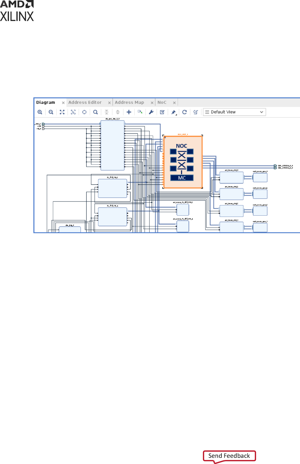
Using SELECTED_SIM_MODEL IP Property
Perform the following steps to change the simulaon model of your IP using
SELECTED_SIM_MODEL:
1. In the Flow Navigator, click Open Block Design to open a block design.
2. Select the desired IP from the block design.
3. Right-click and click Block Properes opon.
Appendix F: SystemC Support in Vivado IDE
UG900 (v2022.1) April 21, 2022 www.xilinx.com
Vivado Design Suite User Guide: Logic Simulation 217
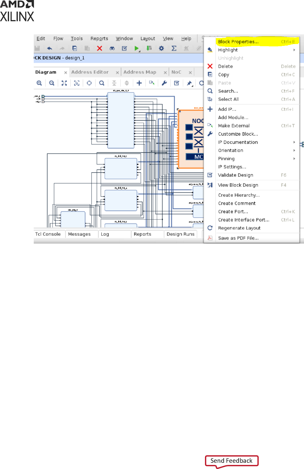
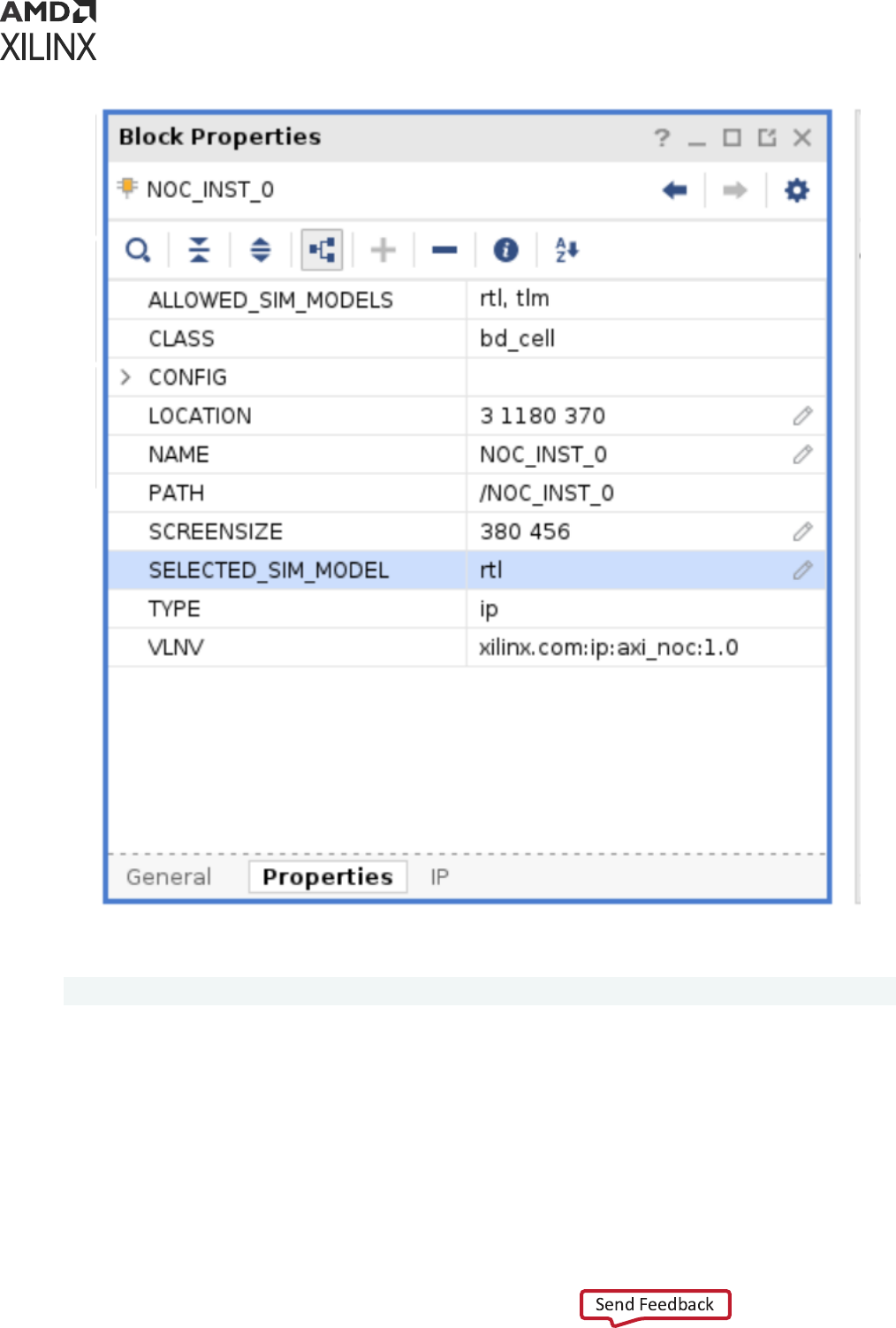
The following Tcl command is an equivalent to change the SELECTED_SIM_MODEL:
set_property SELECTED_SIM_MODEL tlm [get_bd_cells /NOC_INST_0]
Using PREFERRED_SIM_MODEL Project Property
Perform the following steps to change the simulaon model of your IP using
PREFERRED_SIM_MODEL:
1. Click IP opon in the Sengs dialog box.
2. Select tlm from Select preferred simulaon model of IP drop-down menu.
Appendix F: SystemC Support in Vivado IDE
UG900 (v2022.1) April 21, 2022 www.xilinx.com
Vivado Design Suite User Guide: Logic Simulation 219
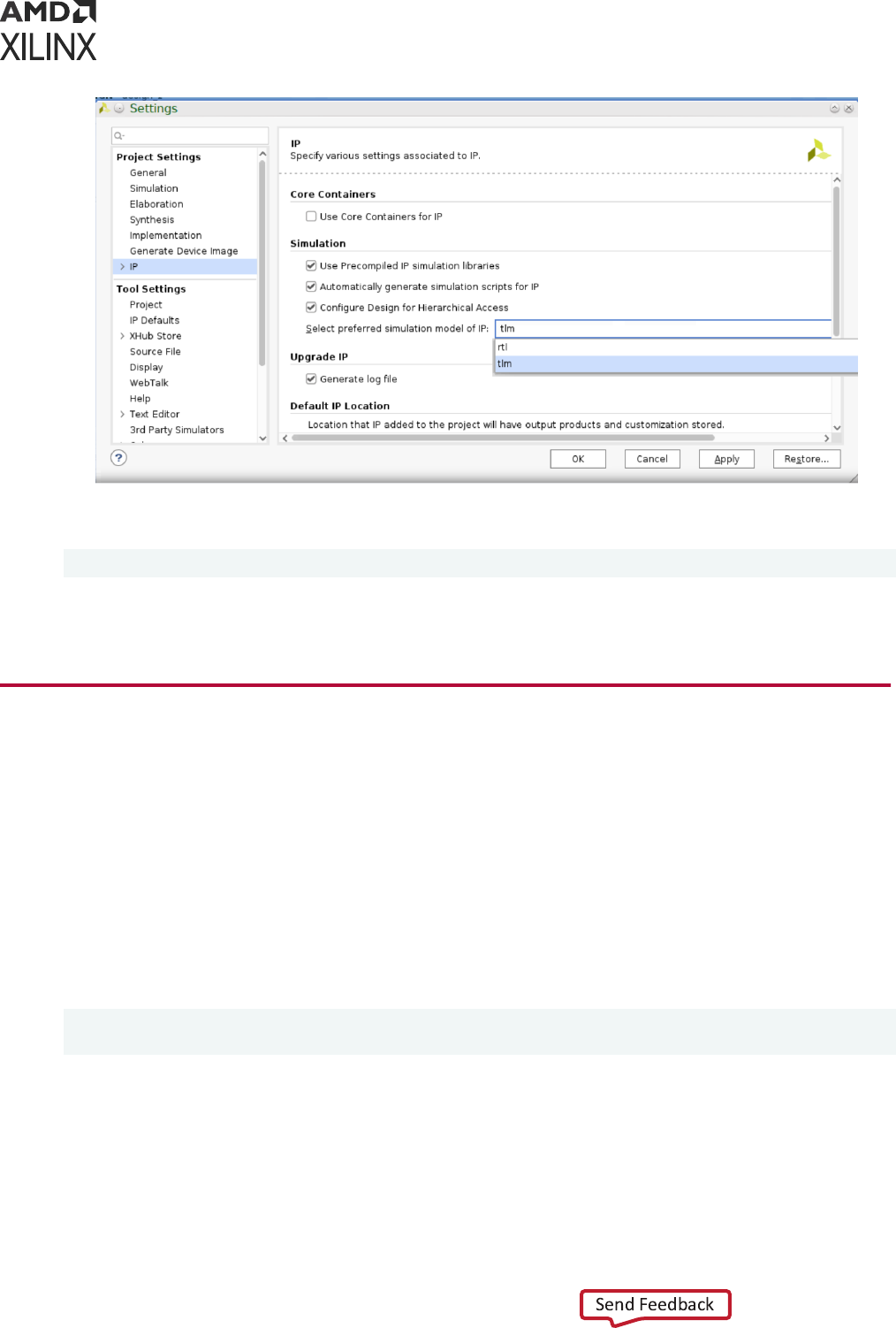
The following Tcl command is an equivalent to change the PREFERRED_SIM_MODEL:
set_property preferred_sim_model tlm [current_project]
Note: Seng PREFFERED_SIM_MODEL to tlm sets all IPs SELECTED_SIM_MODEL to tlm except IPs
which does not support tlm.
Protected Models
The protected models are pre-compiled and released in the form of a shared library that is built
for the respecve simulator. This shared library is packaged as part of the Vivado
®
install and
based on the design conguraon these models are bonded during elaboraon. The following
two protected models are delivered as part of Vivado install:
• AI Engine
• Network on chip (NoC)
These models are in the form of shared library present in the following installaon path:
<Vivado-install-path>/data/simmodels/<simulator>/<simulator_version>/
<os_type>/<gcc_version>/systemc/protected
• Vivado simulator: <Vivado-install-path>/data/simmodels/xsim/2022.1/
lnx64/6.2.0/systemc/protected
• Xcelium simulator: <Vivado-install-path>/data/simmodels/xcelium/
21.009.002/lnx64/9.3.0/systemc/protected
Appendix F: SystemC Support in Vivado IDE
UG900 (v2022.1) April 21, 2022 www.xilinx.com
Vivado Design Suite User Guide: Logic Simulation 220

• Questa Advanced Simulator: <Vivado-install-path>/data/simmodels/questa/
2021.3/lnx64/7.4.0/systemc/protected
• VCS Simulator: <Vivado-install-path>/data/simmodels/vcs/S-2021.09/
lnx64/9.2.0/systemc/protected/
Unprotected Models
The unprotected models are released as a source code in the install. You need to compile the
model for the target simulator using the compile_simlib ulity. For Vivado
®
simulator, these
unprotected models are pre-compiled in the standard <Vivado-install-path>/data/xsim
folder where other libraries are compiled. For third party simulators, these models must be
compiled using compile_simlib. The following un-protected models are delivered as part of
Vivado installaon:
• aie_xtlm
• axi_tg_sc
• axis_dwidth_converter_sc
• axis_switch_sc
• common_cpp
• common_rpc
• debug_tcp_server
• emu_perf_common
• noc_sc
• pl_fileio
• remote_port_c
• remote_port_sc
• rwd_tlmmodel
• sim_ddr
• sim_qdma_cpp
• sim_qdma_sc
• sim_xdma_cpp
• sim_xdma_sc
• tlm_ext
• xtlm
Appendix F: SystemC Support in Vivado IDE
UG900 (v2022.1) April 21, 2022 www.xilinx.com
Vivado Design Suite User Guide: Logic Simulation 221

• xtlm_ap_ctrl
• xtlm_ipc
• xtlm_simple_interconnect
• xtlm_trace_model
These simulaon model sources are present in the following installaon path:
<Vivado-install-path>/data/systemc/
The following IP support SystemC simulaon:
• processing_system7_v5_5_6
• versal_cips_v3_2_0
• zynq_ultra_ps_e_v3_2_6
• zynq_ultra_ps_e_v3_3_8
Note: GCC version to compile these models should be supported version as menoned in this user guide.
SystemC Simulation Using Vivado
Running SystemC simulaon design needs:
• Creang design sources
• Compiling simulaon models using compile_simlib
• Specify tool/design sengs needed
c/c++/SystemC sources can be compiled using GCC. Each simulator supports dierent versions
of GCC. If design contains Xilinx provided SystemC models, GCC version used should be the
supported version. Design needs to be re-compiled if GCC version changes.
Simulators Supported for SystemC Simulation
Following are the simulators supported for SystemC simulaon in the Vivado
®
Design Suite:
Table 42: Simulators Supported for SystemC Simulation
Simulator Version
Compatible GCC
Version
SystemC Compiler
Vivado
®
simulator 2022.1 6.2.0 XSC
Siemens EDA Questa Advanced
simulator
2021.3 7.4.0 SCCOM
Appendix F: SystemC Support in Vivado IDE
UG900 (v2022.1) April 21, 2022 www.xilinx.com
Vivado Design Suite User Guide: Logic Simulation 222

Table 42: Simulators Supported for SystemC Simulation (cont'd)
Simulator Version
Compatible GCC
Version
SystemC Compiler
Cadence Xcelium Parallel simulator 21.09.002 9.3 XMSC
VCS S-2021.09 9.2.0 SYSCAN
Riviera 2021.04 9.3 CCOMP
Simulator Settings for Third-Party Tools
Table 43: Simulator Settings for Third Party Tools
Simulator Linux
Questa
setenv MODEL_TECH <tool installation path>
setenv LM_LICENSE_FILE <license file>
setenv PATH ${MODEL_TECH}/bin:$PATH
Xcelium
setenv CDS_INST_DIR <xcelium_install_dir>
setenv LD_LIBRARY_PATH $CDS_INST_DIR/tools/xcelium/
lib:$LD_LIBRARY_PATH
setenv PATH $CDS_INST_DIR/tools/xcelium/
bin:$CDS_INST_DIR/tools/bin:$PATH
setenv CDS_LICENSE_DIR <tool_license>
VCS
setenv VCS_HOME <tool_install_path>
setenv SYSTEMC_HOME $VCS_HOME/linux64/lib
setenv LM_LICENSE_FILE <license file>
setenv VG_GNU_PACKAGE /tools/installs/synopsys/vg_gnu/
2020.12/linux
setenv PATH ${VCS_HOME}/bin:${PATH}
source $VG_GNU_PACKAGE/source_me[.sh|.csh]
Riviera
source <tool_install_dir>/etc/setenv
source <tool_install_dir>etc/setgcc
export ALDEC_LICENSE_FILE=<tool_license>
Note: By default, GCC path is auto determined from the tool installaon locaon for Questa and Xcelium.
GCC Path Settings
The following table describes GCC executable path sengs for compile_simlib and
launch_simulation:
Table 44:
GCC Path Settings
Command Settings
compile_simlib
• Specify the GCC compiler install path using -gcc_exec_path switch.
• If not, set the environment variable GCC_SIM_EXE_PATH <gcc_install_dir>.
Appendix F: SystemC Support in Vivado IDE
UG900 (v2022.1) April 21, 2022 www.xilinx.com
Vivado Design Suite User Guide: Logic Simulation 223

Table 44: GCC Path Settings (cont'd)
Command Settings
launch_simulation
• Specify the GCC compiler install path using -gcc_install_path switch.
• If not, set the property using set_property
simulator.<name>_gcc_install_dir <gcc_path> [current_project]
• If not, set the environment variable GCC_SIM_EXE_PATH <gcc_install_dir>.
Note: If these recommended sengs are not found, Vivado would pick install path from PATH env variable.
Also, it is always recommended to use tool nave SystemC compilers.
Running SystemC Simulation Using Vivado
Simulator
For step-by-step demonstraon on how to run Vivado
®
simulaon, see Vivado Design Suite User
Guide: Release Notes, Installaon, and Licensing (UG973).
Note: If you are using the Vivado simulator, be sure to specify all appropriate project sengs for your
design before running simulaon.
Appendix F: SystemC Support in Vivado IDE
UG900 (v2022.1) April 21, 2022 www.xilinx.com
Vivado Design Suite User Guide: Logic Simulation 224

Appendix G
Automated Testbench Generation
for Sub-Design
From 2021.2 onwards, new methodology is introduced in Vivado simulator (XSim) to create a
realisc funconal testbench for a language independent sub-design unit. This methodology
currently works for Verilog/VHDL/System Verilog and mixed design of these language. To use
this methodology, two new Tcl commands are introduced. Usage of this new methodology with a
real design is explained in subsequent secons.
generate_vcd_ports
The generate_vcd_port command opens a VCD le handle for wring port acvity of the
given instance. This VCD le is read by create_testbench Tcl command to read port acvity
for wring the smuli source. The instance can be selected from the scope window in the Vivado
simulator IDE or by specifying the hierarchical path to the instance when execung this
command from Tcl console. The command creates dummports.vcd le that gets populated
when running simulaon for the selected instance scope.
Note: The Vivado simulator must be acve to generate this le for the selected instance.
If running this command from Vivado IDE, then the dumpports.vcd le is created in the
simulaon run directory. If running this command from Vivado simulator standalone GUI, then
the dumpports.vcd le is created in vcd2tb sub-directory of the current directory. Following
are the generate_vcd_port opons:
• -scope <arg> (required): Specify the instance scope hierarchy name.
• -quiet (oponal): Execute the command quietly, returning no messages from the command.
The command also returns TCL_OK regardless of any errors encountered during execuon.
Note: Any errors encountered on the command-line while launching the command are returned. Only
errors occurring inside the command are trapped.
• -verbose (oponal): Temporarily override any message limits and return all messages from this
command.
Note: Message limits can be dened with the set_msg_config command.
Appendix G: Automated Testbench Generation for Sub-Design
UG900 (v2022.1) April 21, 2022 www.xilinx.com
Vivado Design Suite User Guide: Logic Simulation 225

Following example command creates a VCD le for /top/DUT/fifo/buf_1 instance of type
buf module, record waveform acvity for 2000ns, and close the VCD le handle:
generate_vcd_ports {/top/DUT/fifo/buf_1}
run 2000ns
close_vcd -ports
create_testbench
Create testbench for a design unit instance. This command creates a funconal system verilog
based testbench for the scoped hierarchical instance. The testbench contains port/signal
specicaon, parameter declaraon, smuli vector include le, and module instanaon of the
selected instance as design under test (DUT). This command allows you to add the testbench to
an exisng or a new simulaon leset from which the simulaon can be launched.
Note: The generated testbench is simulator independent.
Table 45: create_testbench Command Options
Option Description
-name <arg> Specify the name of the testbench module name. Default name is testbench.
-add_to_simset <arg> Specify simulation fileset name to which the testbench needs to be added. If this
switch is not specified, then the command adds testbench to the current active
simulation fileset.
-set_as_top Set the generated testbench module at the top in the simulation fileset where the
testbench is added.
-mode <arg> Specifies simulation mode. Allowed values are behavioral, post-synthesis, or post-
implementation. Default is behavioral.
-type <arg> Specifies simulation type. Allowed values are functional or timing (not applicable
for behavioral mode).
-force Overwrite existing testbench file.
-quiet Execute the command quietly, returning no messages from the command. The
command also returns TCL_OK regardless of any errors encountered during
execution.
Note: Any errors encountered on the command-line while launching the command
are returned. Only errors occurring inside the command are trapped.
-verbose Temporarily override any message limits and return all messages from this
command.
Note: Message limits can be defined with the set_msg_config command.
Notes:
1. All the arguments are optional as default value is set as explained for each flag.
Appendix G: Automated Testbench Generation for Sub-Design
UG900 (v2022.1) April 21, 2022 www.xilinx.com
Vivado Design Suite User Guide: Logic Simulation 226
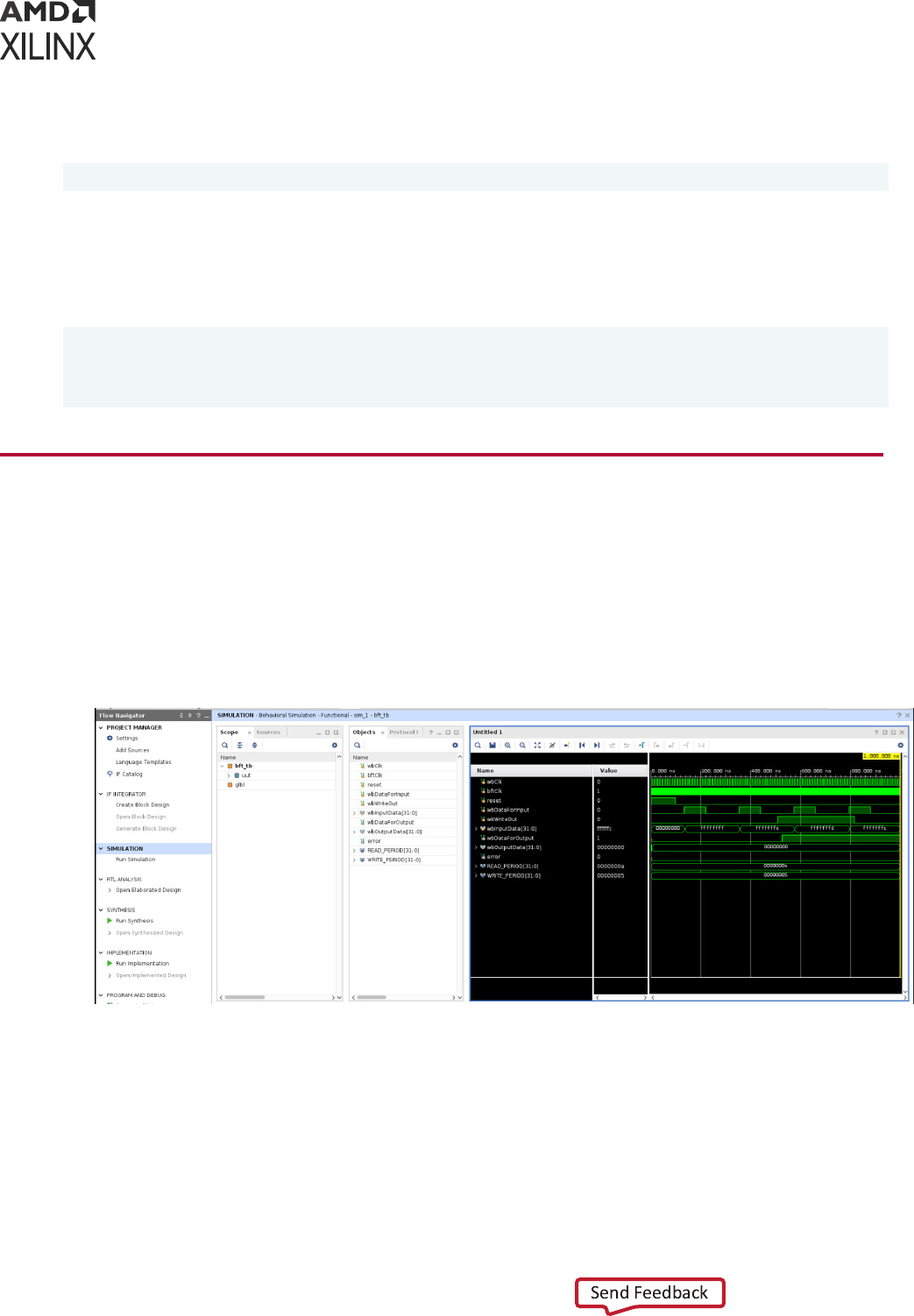
The following example command creates a testbench for fo module and adds it to the
sub_design_fifo simulaon leset:
create_testbench -name fifo -add_to_simset sub_design_fifo
The following example command generates VCD le for /top/DUT/fifo/buf_1 instance of
type buf module, record the waveform acvity in the VCD le for 2000ns, create a testbench
with module named tb, add the testbench to the test_buffer simulaon leset and set tb as
top module in this leset:
generate_vcd_ports {/top/DUT/fifo/buf_1}
run 2000ns
close_vcd -ports
create_testbench -name tb -add_to_simset test_buffer -set_as_top
Using Automated Testbench Generation on
Example Design
For demo purpose, let us use the BFT example design shipped with Vivado IDE.
1. Open the BFT example design in Vivado IDE.
2. Call launch_simulation with Vivado as the selected simulator. You should see the ports
shown in the following waveform.
3. Select the desired scope for which you want to generate testbench as shown in the following
gure:
Appendix G: Automated Testbench Generation for Sub-Design
UG900 (v2022.1) April 21, 2022 www.xilinx.com
Vivado Design Suite User Guide: Logic Simulation 227
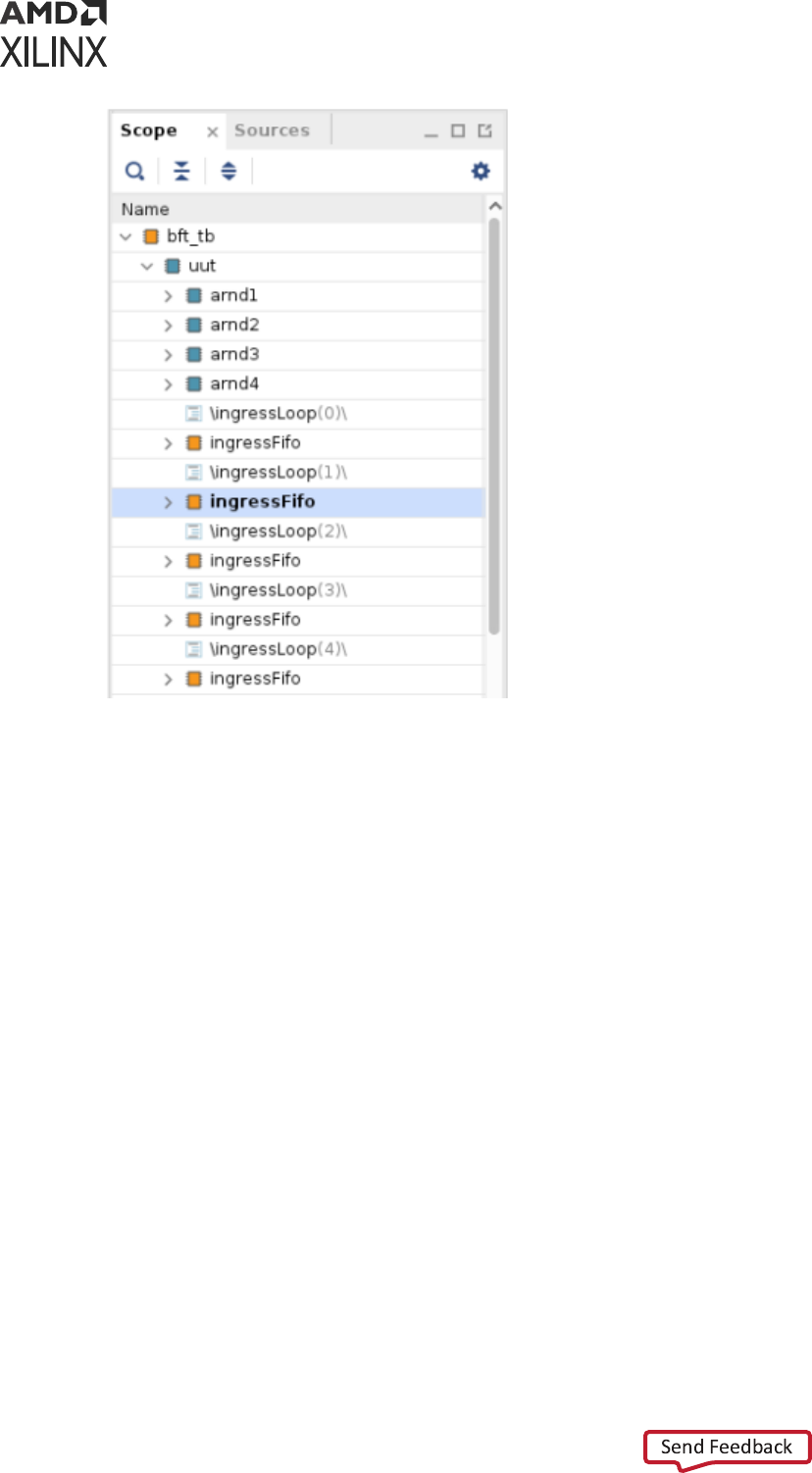
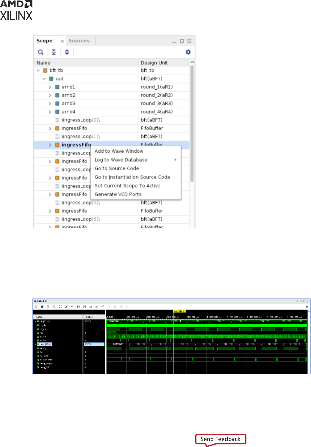
5. Delete all exisng signals on the waveform and select Add to Wave Window for the selected
scope.
Note: Step 5 will be used to demonstrate that the generated testbench is driving the design unit
correctly.
6. Use restart, run 2000 ns and close_vcd -ports commands on Tcl console to dump
the signal acvity. This logs the signal from me 0 to 2000 ns on the waveform as shown in
the following gure:
7. Use create_testbench -name demo_tb -add_to_simset demo_simset -
set_as_top command on Tcl console to generate testbench. This creates your testbench
with the module name demo_tb and creates a demo_simset with this testbench as top
module.
Appendix G: Automated Testbench Generation for Sub-Design
UG900 (v2022.1) April 21, 2022 www.xilinx.com
Vivado Design Suite User Guide: Logic Simulation 229
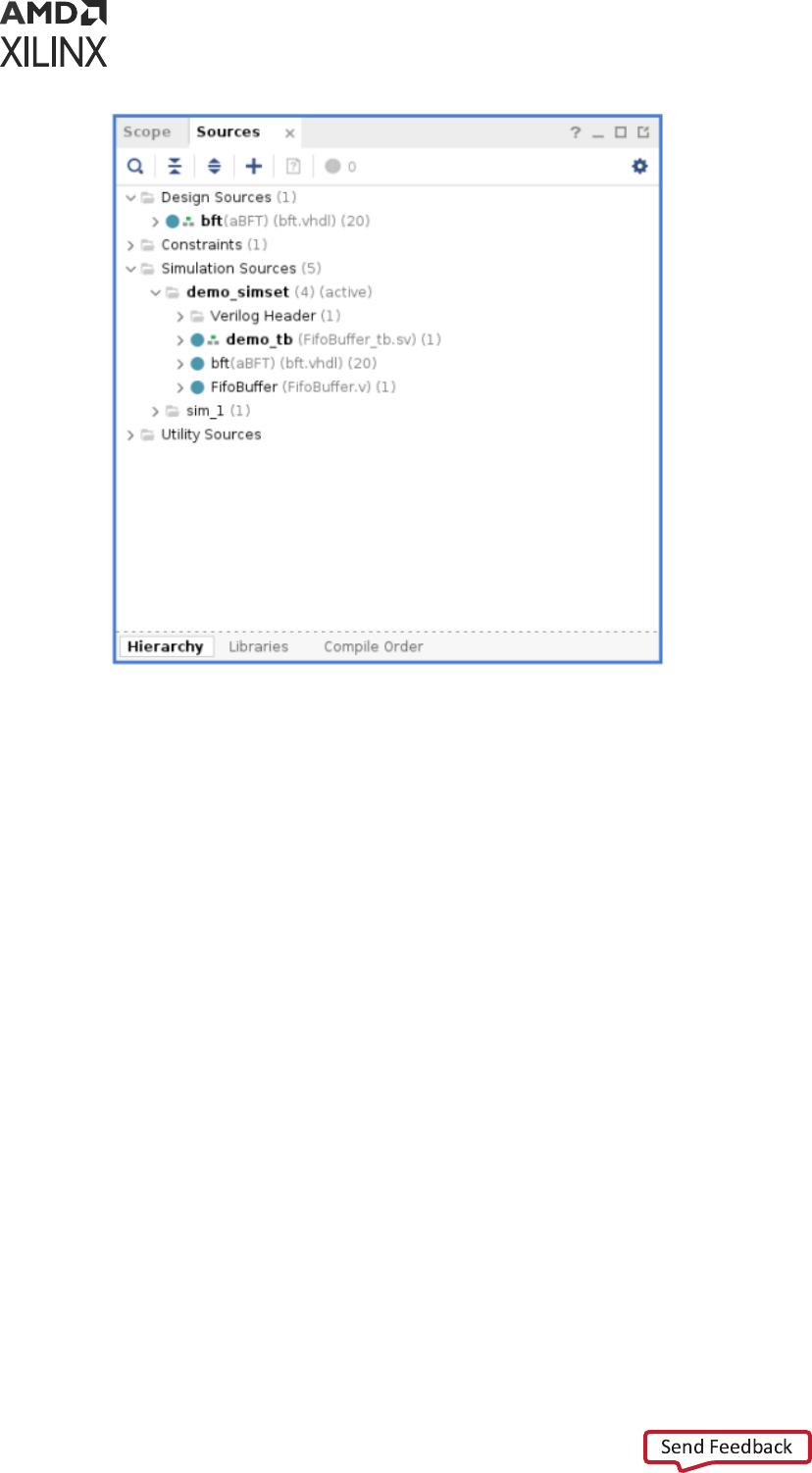
8. Use launch_simulation command to run simulaon with the newly generated testbench.
9. Compare the input/output of the waveform with waveform of your original design, noce
that the input/output are same.
This is how you can create testbench for your sub-design and use the generated testbench
independently with any standard simulator.
Appendix G: Automated Testbench Generation for Sub-Design
UG900 (v2022.1) April 21, 2022 www.xilinx.com
Vivado Design Suite User Guide: Logic Simulation 230

Appendix H
Handling Special Cases
Using Global Reset and 3-State
Xilinx devices have dedicated roung and circuitry that connect to every register in the device.
Global Set and Reset Net
During conguraon, the dedicated Global Set/Reset (GSR) signal is asserted. The GSR signal is
deasserted upon compleon of device conguraon. All the ip-ops and latches receive this
reset, and are set or reset depending on how the registers are dened.
Although you can access the GSR net aer conguraon, avoid use of the GSR circuitry in place
of a manual reset. This is because the FPGA devices oer high-speed backbone roung for high
fanout signals such as a system reset. This backbone route is faster than the dedicated GSR
circuitry, and is easier to analyze than the dedicated global roung that transports the GSR signal.
In post-synthesis and post-implementaon simulaons, the GSR signal is automacally asserted
for the rst 100 ns to simulate the reset that occurs aer conguraon.
A GSR pulse can oponally be supplied in pre-synthesis funconal simulaons, but is not
necessary if the design has a local reset that resets all registers.
TIP:
When you create a test bench, remember that the GSR pulse occurs automacally in the post-
synthesis and post-implementaon simulaon. This holds all registers in reset for the rst 100 ns of the
simulaon.
Note
: If a design uses ICAP primive, GSR will last for 1.281 us at that me.
Global 3-State Net
In addion to the dedicated global GSR, output buers are set to a high impedance state during
conguraon mode with the dedicated Global 3-state (GTS) net. All general-purpose outputs are
aected whether they are regular, 3-state, or bidireconal outputs during normal operaon. This
ensures that the outputs do not erroneously drive other devices as the FPGA is congured.
Appendix H: Handling Special Cases
UG900 (v2022.1) April 21, 2022 www.xilinx.com
Vivado Design Suite User Guide: Logic Simulation 231
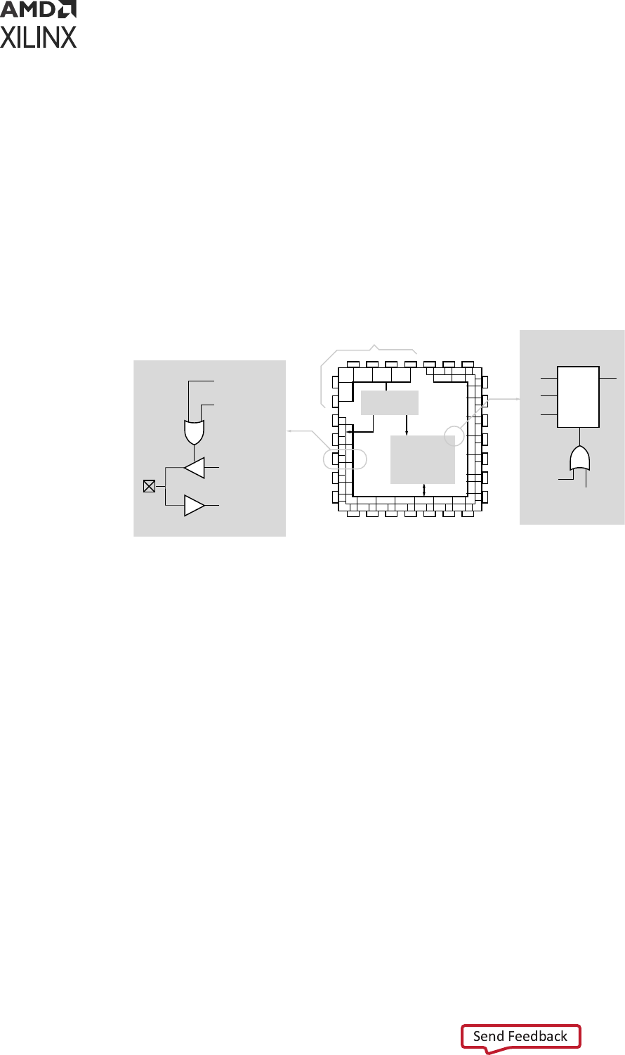
In simulaon, the GTS signal is usually not driven. The circuitry for driving GTS is available in the
post-synthesis and post-implementaon simulaons and can be oponally added for the pre-
synthesis funconal simulaon, but the GTS pulse width is set to 0 by default.
Using Global 3-State and Global Set and Reset
Signals
The following gure shows how Global 3-State (GTS) and Global Set/Reset (GSR) signals are used
in an FPGA.
Figure 53: Built-in FPGA Initialization Circuitry Diagram
X8352
User
Programmable
Latch/Register
Global Tri-State
(GTS)
User Output
I/O
Pad
Output Buffer
Input Buffer
User Input
User Tri-State
Enable
General Purpose
I/Os Used for
Initialization
GTS
GSR
User
Async.
Reset
Global
Set/Reset
(GSR)
Initialization
Controller
User
Programmable
Logic
Resources
Q
D
CLR
C
CE
Global Set and Reset and Global 3-State Signals in
Verilog
The GSR and GTS signals are dened in the <Vivado_Install_Dir>/data/verilog/src/
glbl.v module.
In most cases, GSR and GTS need not be dened in the test bench.
The glbl.v le declares the global GSR and GTS signals and automacally pulses GSR for 100
ns.
Global Set and Reset and Global 3-State Signals in
VHDL
The GSR and GTS signals are dened in the le: <Vivado_Install_Dir>/data/vhdl/src/
unisims/primitive/GLBL_VHD.vhd.
To use the GLBL_VHD component you must instanate it into the test bench.
Appendix H: Handling Special Cases
UG900 (v2022.1) April 21, 2022 www.xilinx.com
Vivado Design Suite User Guide: Logic Simulation 232

The GLBL_VHD component declares the global GSR and GTS signals and automacally pulses
GSR for 100 ns.
The following code snippet shows an example of instanang the GLBL_VHD component in the
test bench and changing the asseron pulse width of the Reset on Conguraon (ROC) to 90 ns:
GLBL_VHD inst:GLBL_VHD generic map (ROC_WIDTH => 90000);
Delta Cycles and Race Conditions
This user guide describes event-based simulators. Event-based simulators can process mulple
events at a given simulaon me. While these events are being processed, the simulator cannot
advance the simulaon me. This event processing me is commonly referred to as delta cycles.
There can be mulple delta cycles in a given simulaon me step.
Simulaon me is advanced only when there are no more transacons to process for the current
simulaon me. For this reason, simulators can give unexpected results, depending on when the
events are scheduled within a me step. The following VHDL coding example shows how an
unexpected result can occur.
VHDL Coding Example With Unexpected Results
clk_b <= clk;
clk_prcs : process (clk)
begin
if (clk'event and clk='1') then
result <= data;
end if;
end process;
clk_b_prcs : process (clk_b)
begin
if (clk_b'event and clk_b='1') then
result1 <= result;
end if;
end process;
In this example, there are two synchronous processes:
• clk_prcs
• clk_b_prcs
The simulator performs the clk_b <= clk assignment before advancing the simulaon me.
As a result, events that should occur in two clock edges occur in one clock edge instead, causing
a race condion.
Recommended ways to introduce causality in simulators for such cases include:
Appendix H: Handling Special Cases
UG900 (v2022.1) April 21, 2022 www.xilinx.com
Vivado Design Suite User Guide: Logic Simulation 233

• Do not change clock and data at the same me. Insert a delay at every output.
• Use the same clock.
• Force a delta delay by using a temporary signal, as shown in the following example:
clk_b <= clk;
clk_prcs : process (clk)
begin
if (clk'event and clk='1') then
result <= data;
end if;
end process;
result_temp <= result;
clk_b_prcs : process (clk_b)
begin
if (clk_b'event and clk_b='1') then
result1 <= result_temp;
end if;
end process;
Most event-based simulators can display delta cycles. Use this to your advantage when
debugging simulaon issues.
Using the ASYNC_REG Constraint
The ASYNC_REG constraint:
• Idenes asynchronous registers in the design
• Disables X propagaon for those registers
The ASYNC_REG constraint can be aached to a register in the front-end design by using either:
• An aribute in the HDL code
• A constraint in the Xilinx Design Constraints (XDC)
The registers to which ASYNC_REG are aached retain the previous value during ming
simulaon, and do not output an X to simulaon. Use care; a new value might have been clocked
in as well.
The ASYNC_REG constraint is applicable to CLB and Input Output Block (IOB) registers and
latches only. For more informaon, see ASYNC_REG constraint at this link in the Vivado Design
Suite Properes Reference Guide (UG912).
Appendix H: Handling Special Cases
UG900 (v2022.1) April 21, 2022 www.xilinx.com
Vivado Design Suite User Guide: Logic Simulation 234

If you cannot avoid clocking in asynchronous data, do so for IOB or CLB registers only. Clocking
in asynchronous signals to RAM, Shi Register LUT (SRL), or other synchronous elements has less
determinisc results; therefore, should be avoided. Xilinx highly recommends that you rst
properly synchronize any asynchronous signal in a register, latch, or FIFO before wring to a
RAM, Shi Register LUT (SRL), or any other synchronous element. For more informaon, see the
Vivado Design Suite User Guide: Using Constraints (UG903).
Disabling X Propagation for Synchronous Elements
When a ming violaon occurs during a ming simulaon, the default behavior of a latch,
register, RAM, or other synchronous elements is to output an X to the simulator. This occurs
because the actual output value is not known. The output of the register could:
• Retain its previous value
• Update to the new value
• Go metastable, in which a denite value is not seled upon unl some me aer the clocking
of the synchronous element
Because this value cannot be determined, and accurate simulaon results cannot be guaranteed,
the element outputs an X to represent an unknown value. The X output remains unl the next
clock cycle in which the next clocked value updates the output if another violaon does not
occur.
The presence of an X output can signicantly aect simulaon. For example, an X generated by
one register can be propagated to others on subsequent clock cycles. This can cause large
porons of the design under test to become unknown.
To correct X-generaon:
• On a synchronous path, analyze the path and x any ming problems associated with this or
other paths to ensure a properly operang circuit.
• On an asynchronous path, if you cannot otherwise avoid ming violaons, disable the X
propagaon on synchronous elements during ming violaons by using the ASYNC_REG
property.
When X propagaon is disabled, the previous value is retained at the output of the register. In
the actual silicon, the register might have changed to the 'new' value. Disabling X propagaon
might yield simulaon results that do not match the silicon behavior.
CAUTION!
Exercise care when using this opon. Use it only if you cannot otherwise avoid ming
violaons.
Appendix H: Handling Special Cases
UG900 (v2022.1) April 21, 2022 www.xilinx.com
Vivado Design Suite User Guide: Logic Simulation 235

Simulating Configuration Interfaces
This secon describes the simulaon of the following conguraon interfaces:
• JTAG simulaon
• SelectMAP simulaon
JTAG Simulation
BSCAN component simulaon is supported on all devices.
The simulaon supports the interacon of the JTAG ports and some of the JTAG operaon
commands. The JTAG interface, including interface to the scan chain, is not fully supported. To
simulate this interface:
1. Instanate the BSCANE2 component and connect it to the design.
2. Instanate the JTAG_SIME2 component into the test bench (not the design).
This becomes:
• The interface to the external JTAG signals (such as TDI, TDO, and TCK)
• The communicaon channel to the BSCAN component
The communicaon between the components takes place in the VPKG VHDL package le or the
glbl Verilog global module. Accordingly, no implicit connecons are necessary between the
specic JTAG_SIME2 component and the design, or the specic BSCANE2 symbol.
Smulus can be driven and viewed from the specic JTAG_SIME2 component within the test
bench to understand the operaon of the JTAG/BSCAN funcon. Instanaon templates for
both of these components are available in both the Vivado
®
Design Suite templates and the
specic-device libraries guides.
SelectMAP Simulation
The conguraon simulaon models (SIM_CONFIGE2 and SIM_CONFIGE3) with an
instanaon template allow supported conguraon interfaces to be simulated to ulmately
show the DONE pin going HIGH. This is a model of how the supported devices react to smulus
on the supported conguraon interface.
The following table lists the supported interfaces and devices.
Appendix H: Handling Special Cases
UG900 (v2022.1) April 21, 2022 www.xilinx.com
Vivado Design Suite User Guide: Logic Simulation 236
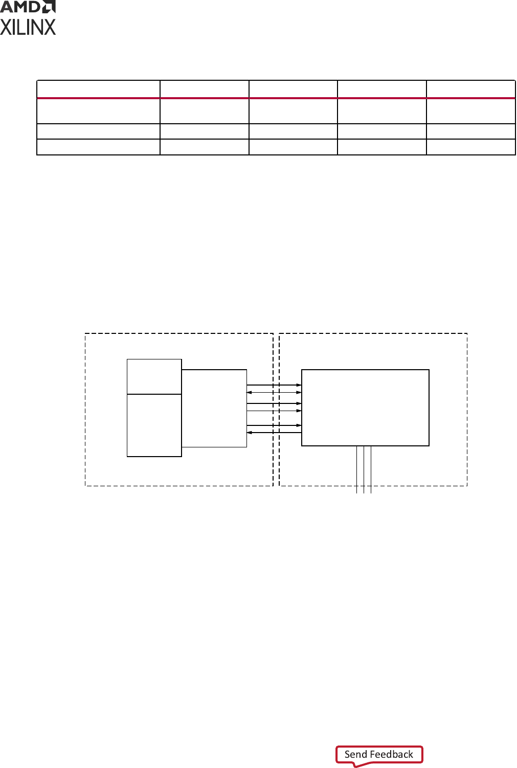
Table 46: Supported Configuration Devices and Modes
Devices SelectMAP Serial SPI BPI
7 series and Zynq
®
-7000 SoC
Devices
Yes Yes No No
UltraScale Devices Yes Yes No No
UltraScale+™ Devices Yes Yes No No
The models handle control signal acvity as well as bit le downloading. Internal register sengs
such as the CRC, IDCODE, and status registers are included. You can monitor the Sync Word as it
enters the device and the start-up sequence as it progresses. The following gure illustrates how
the system should map from the hardware to the simulaon environment.
The conguraon process is specically outlined in the conguraon user guides for each device.
These guides contain informaon on the conguraon sequence, as well as the conguraon
interfaces.
Figure 54: Block Diagram of Model Interaction
Host Controller - Input Stimulus to Model
Configuration Simulation Model
IDCODE Parameter
Memory
Controller
Target FPGA
Bit File
User
Memory
SelectMAP
Control
Logic
CCLK
Data [0-n]
RDWR
PROG_B
INIT_B
CS
Mode Pins [2:0]
1 1 0
X10194
System Level Description
The conguraon models allow the conguraon interface control logic to be tested before the
hardware is available. It simulates the enre device, and is used at a system level for:
• Applicaons using a processor to control the conguraon logic to ensure proper wiring,
control signal handling, and data input alignment.
• Applicaons that control the data loading process with the CS (SelectMAP Chip Select) or CLK
signal to ensure proper data alignment.
• Systems that need to perform a SelectMAP ABORT or Readback.
Appendix H: Handling Special Cases
UG900 (v2022.1) April 21, 2022 www.xilinx.com
Vivado Design Suite User Guide: Logic Simulation 237

The config_test_bench.zip le has sample test benches that simulate a processor running
the SelectMAP logic. These test benches have control logic to emulate a processor controlling
the SelectMAP interface, and include features such as a full conguraon, ABORT, and Readback
of the IDCODE and status registers.
For the ZIP les associated with this model, see Xilinx Answer Record 53632.
The simulated host system must have a method for le delivery as well as control signal
management. These control systems should be designed as set forth in the device conguraon
user guides.
The conguraon models also demonstrate what is occurring inside the device during the
conguraon procedure when a BIT le is loaded into the device.
During the BIT le download, the model processes each command and changes registers sengs
that mirror the hardware changes.
You can monitor the CRC register as it acvely accumulates a CRC value. The model also shows
the Status Register bits being set as the device progresses through the dierent states of
conguraon.
Debugging with the Model
Each conguraon model provides an example of a correct conguraon. You can leverage this
example to assist in the debug procedure if you encounter device programming issues.
You can read the Status Register through JTAG using the Vivado Device Programmer tool. This
register contains informaon relang to the current status of the device and is a useful
debugging resource. If you encounter issues on the board, reading the Status Register in Vivado
Device Programmer is one of the rst debugging steps to take.
Aer the status register is read, you can map it to the simulaon to pinpoint the conguraon
stage of the device.
For example, the GHIGH bit is set HIGH aer the data load process completes successfully; if this
bit is not set, then the data loading operaon did not complete. You can also monitor the GTW,
GWE, and DONE signals set in BitGen that are released in the start-up sequence.
The conguraon models also allow for error injecon. The acve CRC logic detects any issue if
the data load is paused and started again with any problems. It also detects bit ips manually
inserted in the BIT le, and handles them just as the device would handle this error.
Feature Support
Each device-specic conguraon user guide outlines the supported methods of interacng with
each conguraon interface.The table below shows which features discussed in the conguraon
user guides are supported.
Appendix H: Handling Special Cases
UG900 (v2022.1) April 21, 2022 www.xilinx.com
Vivado Design Suite User Guide: Logic Simulation 238
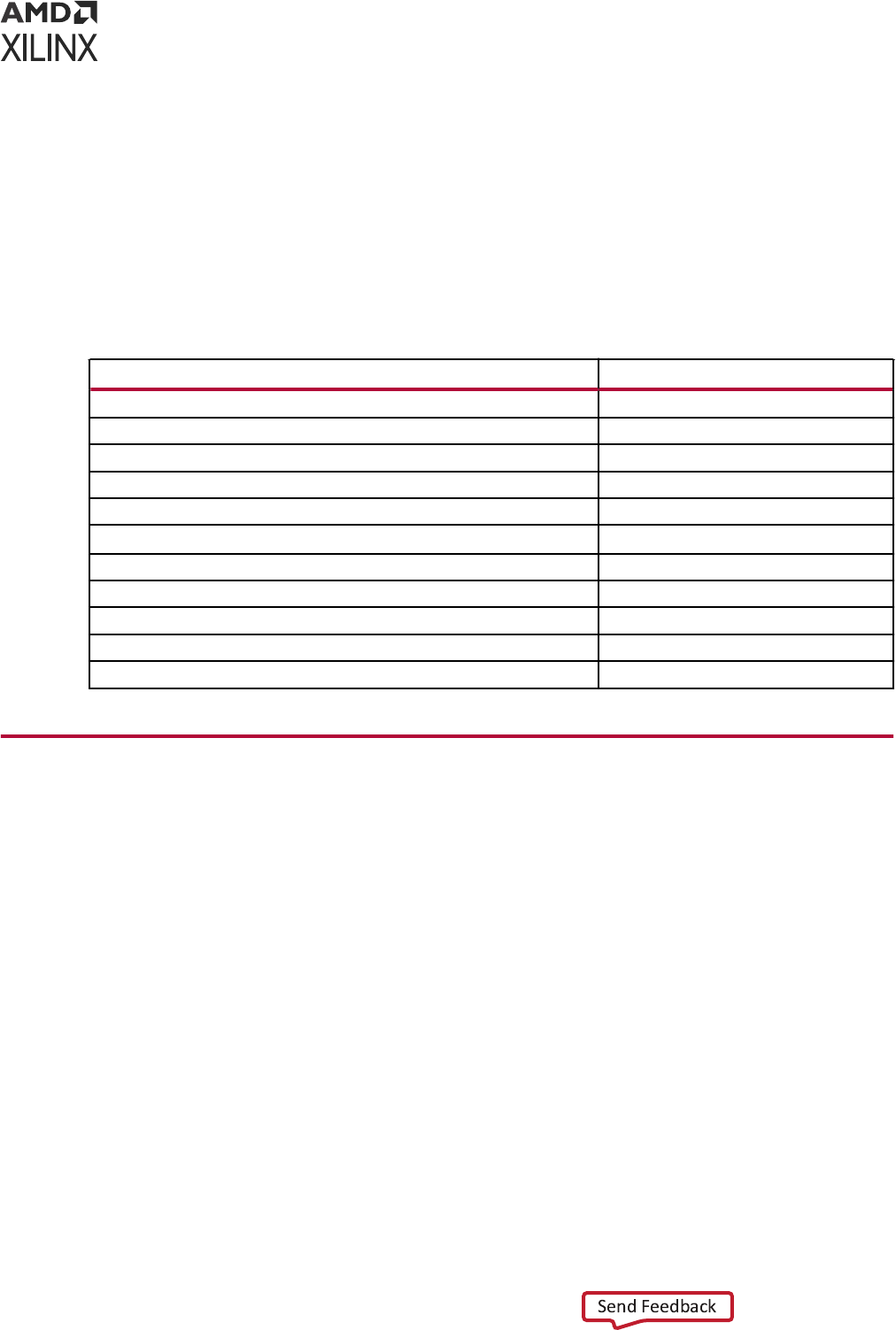
The SIM_CONFIGE2 model:
• Does not support Readback of conguraon data.
• Does not store conguraon data provided, although it does calculate a CRC value.
• Can perform Readback on specic registers only to ensure that a valid command sequence
and signal handling is provided to the device.
• Is not intended to allow Readback data les to be produced.
Table 47: Model-Supported Slave SelectMAP and Serial Features
Slave SelectMAP and Serial Features Supported
Master mode No
Daisy chain - slave parallel daisy chains No
SelectMAP data loading Yes
Continuous SelectMAP data loading Yes
Non-continuous SelectMAP data loading Yes
SelectMAP ABORT Yes
SelectMAP reconfiguration No
SelectMAP data ordering Yes
Reconfiguration and MultiBoot No
Configuration CRC—CRC checking during configuration Yes
Configuration CRC—post-configuration CRC No
Disabling Block RAM Collision Checks for
Simulation
Xilinx
®
block RAM memory is a true dual-port RAM where both ports can access any memory
locaon at any me. Be sure that the same address space is not accessed for reading and wring
at the same me. This causes a block RAM address collision. These are valid collisions, because
the data that is being read from the read port is not valid.
In the hardware, the value that is read might be the old data, the new data, or a combinaon of
the old data and the new data.
In simulaon, this is modeled by outpung X because the value read is unknown. For more
informaon on block RAM collisions, see the user guide for the device.
In certain applicaons, this situaon cannot be avoided or designed around. In these cases, the
block RAM can be congured not to look for these violaons. This is controlled by the generic
(VHDL) or parameter (Verilog) SIM_COLLISION_CHECK string in block RAM primives.
Appendix H: Handling Special Cases
UG900 (v2022.1) April 21, 2022 www.xilinx.com
Vivado Design Suite User Guide: Logic Simulation 239

The following table shows the string opons you can use with SIM_COLLISION_CHECK to
control simulaon behavior in the event of a collision.
Table 48: SIM_COLLISION_CHECK Strings
String
Write Collision
Messages
Write Xs on the Output
ALL Yes Yes
WARNING_ONLY Yes No. Applies only at the time of collision. Subsequent reads of
the same address space could produce Xs on the output.
GENERATE_X_ONLY No Yes
None No No. Applies only at the time of collision. Subsequent reads of
the same address space could produce Xs on the output.
Apply the SIM_COLLISION_CHECK at an instance level so you can change the seng for each
block RAM instance.
Dumping the Switching Activity Interchange
Format File for Power Analysis
• Vivado simulator: Power Analysis Using Vivado Simulator
• Dumping SAIF for Power Analysis, and Dumping SAIF in VCS in Chapter 3: Simulang with
Third-Party Simulators
Skipping Compilation or Simulation
Skipping Compilation
You can run simulaon on an exisng snapshot and skip the compilaon (or recompilaon) of the
design by seng the SKIP_COMPILATION property on the simulaon leset:
set_property SKIP_COMPILATION 1 [get_filesets sim_1]
Note: Any change to design les aer the last compilaon is not reected in simulaon when you set this
property.
Appendix H: Handling Special Cases
UG900 (v2022.1) April 21, 2022 www.xilinx.com
Vivado Design Suite User Guide: Logic Simulation 240

Skipping Simulation
To perform a semanc check on the design HDL les, by elaborang and compiling the
simulaon snapshot without running simulaon, you can set the SKIP_SIMULATION property on
the simulaon leset:
set_property SKIP_SIMULATION true [get_filesets sim_1]
IMPORTANT! If you elect to use one of the properes above, disable the Clean up simulaon les check
box in the simulaons sengs, or if you are running in batch/Tcl mode, call
launch_simulation
with
-noclean_dir
.
Appendix H: Handling Special Cases
UG900 (v2022.1) April 21, 2022 www.xilinx.com
Vivado Design Suite User Guide: Logic Simulation 241

Appendix I
Value Rules in Vivado Simulator Tcl
Commands
This appendix contains the value rules that apply to both the add_force and the set_value
Tcl commands.
String Value Interpretation
The interpretaon of the value string is determined by the declared type of the HDL object and
the -radix command line opon. The -radix always overrides the default radix determined by
the HDL object type.
• For HDL objects of type logic, the value is a one-dimensional array of the logic type or
the value is a string of digits of the specied radix.
○ If the string species less bits than the type expects, the string is implicitly zero-extended
(not sign-extended) to match the length of the type.
○ If the string species more bits than the type expects, the extra bits on the MSB side must
be zero; otherwise the command generates a size mismatch error.
For example: The value 3F species 8 bits (4 per hex digit) with radix hex and a 6 bit logic
array, equivalent to binary 0011 1111. But, because the upper two bits of 3 are zero, the
value can be assigned to the HDL object. In contrast, the value 7F would generate an error,
because the upper two bits are not zero.
○ A scalar (not array or record) logic HDL object has an implicit length of 1 bit.
○ For a logic array declared as a [left:right] (Verilog) or a(left TO/DOWNTO
right), the le-most value bit (aer extension/truncaon) is assigned to a[left] and
the right-most value bit is assigned to a[right].
Vivado Design Suite Simulation Logic
The logic is not a concept dened in HDL but is a heurisc introduced by the Vivado
®
simulator.
Appendix I: Value Rules in Vivado Simulator Tcl Commands
UG900 (v2022.1) April 21, 2022 www.xilinx.com
Vivado Design Suite User Guide: Logic Simulation 242

• A Verilog object is considered to be of logic type if it is of the implicit Verilog bit type, which
includes wire and reg objects, as well as integer and me.
• A VHDL object is considered to be of logic type if the objects type is bit, std_logic, or
any enumeraon type whose enumerators are a subset of those of std_logic and include at
least 0 and 1, or type of the object is a one-dimensional array of such a type.
• For HDL objects, which are of VHDL enumeraon type, the value can be one of the
enumerator literals, without single quotes if the enumerator is a character literal. Radix is
ignored.
• For VHDL objects, of integral type, the value can be a signed decimal integer in the range of
the type. Radix is ignored.
• For VHDL and Verilog oang point types the value can be a oang point value. Radix is
ignored.
• For all other types of HDL objects, the Tcl command set does not support seng values.
Appendix I: Value Rules in Vivado Simulator Tcl Commands
UG900 (v2022.1) April 21, 2022 www.xilinx.com
Vivado Design Suite User Guide: Logic Simulation 243

Appendix J
Vivado Simulator Mixed Language
Support and Language Exceptions
The Vivado Integrated Design Environment (IDE) supports the following languages:
• VHDL, see EEE Standard VHDL Language Reference Manual (IEEE-STD-1076-1993)
• Verilog, see IEEE Standard Verilog Hardware Descripon Language (IEEE-STD-1364-2001)
• SystemVerilog Synthesizable subset. See IEEE Standard for SystemVerilog--Unied Hardware
Design, Specicaon, and Vericaon Language (IEEE-STD-1800-2009)
• IEEE P1735 encrypon, see Recommended Pracce for Encrypon and Management of
Electronic Design Intellectual Property (IP) (IEEE-STD-P1735)
This appendix lists the applicaon of Mixed Language in the Vivado simulator, and the excepons
to Verilog, SystemVerilog, and VHDL support.
Using Mixed Language Simulation
The Vivado simulator supports mixed language project les and mixed language simulaon. This
lets you include Verilog/SystemVerilog (SV) modules in a VHDL design, and vice versa.
Restrictions on Mixed Language in Simulation
• A VHDL design can instanate Verilog/SystemVerilog (SV) modules and a Verilog/SV design
can instanate VHDL components. Component instanaon-based default binding is used for
binding a Verilog/SV module to a VHDL component. Any other kind of mixed use of VHDL
and Verilog, such as VHDL process calling a Verilog funcon, is not supported.
• A subset of VHDL types, generics, and ports are allowed on the boundary to a Verilog/SV
module. Similarly, a subset of Verilog/SV types, parameters and ports are allowed on the
boundary to VHDL components. See Table 50: Supported VHDL and Verilog Data Types.
IMPORTANT!
Connecng whole VHDL record object to a Verilog object is unsupported; however,
VHDL record elements of a supported type can be connected to a compable Verilog port.
• A Verilog/SV hierarchical reference cannot refer to a VHDL unit nor can a VHDL expanded or
selected name refer to a Verilog/SV unit.
Appendix J: Vivado Simulator Mixed Language Support and Language Exceptions
UG900 (v2022.1) April 21, 2022 www.xilinx.com
Vivado Design Suite User Guide: Logic Simulation 244

Key Steps in a Mixed Language Simulation
1. Oponally, specify the search order for VHDL components or Verilog/SV modules in the
design libraries of a mixed language project.
2. Use xelab -L to specify the binding order of a VHDL component or a Verilog/SV module in
the design libraries of a mixed language project.
Note: The library search order specied by -L is used for binding Verilog modules to other Verilog
modules as well.
Mixed Language Binding and Searching
When you instanate a VHDL component in a Verilog/SV module or a Verilog/SV module in a
VHDL architecture, the xelab command:
• First searches for a unit of the same language as that of the instanang design unit.
• If a unit of the same language is not found, xelab searches for a cross-language design unit in
the libraries specied by the -L opon.
The search order is the same as the order of appearance of libraries on the xelab command line.
Note: When using the Vivado IDE, the library search order is specied automacally. No user intervenon
is necessary or possible.
Related Information
Verilog Search Order
Instantiating Mixed Language Components
In a mixed language design, you can instanate a Verilog/SV module in a VHDL architecture or a
VHDL component in a Verilog/SV module as described in the following subsecons.
To ensure that you are correctly matching port types, review the Port Mapping and Supported
Port Types.
Instantiating a Verilog Module in a VHDL Design Unit
1. Declare a VHDL component with the same name and in the same case as the Verilog module
that you want to instanate. For example:
COMPONENT MY_VHDL_UNIT PORT (
Q : out STD_ULOGIC;
D : in STD_ULOGIC;
C : in STD_ULOGIC );
END COMPONENT;
Appendix J: Vivado Simulator Mixed Language Support and Language Exceptions
UG900 (v2022.1) April 21, 2022 www.xilinx.com
Vivado Design Suite User Guide: Logic Simulation 245
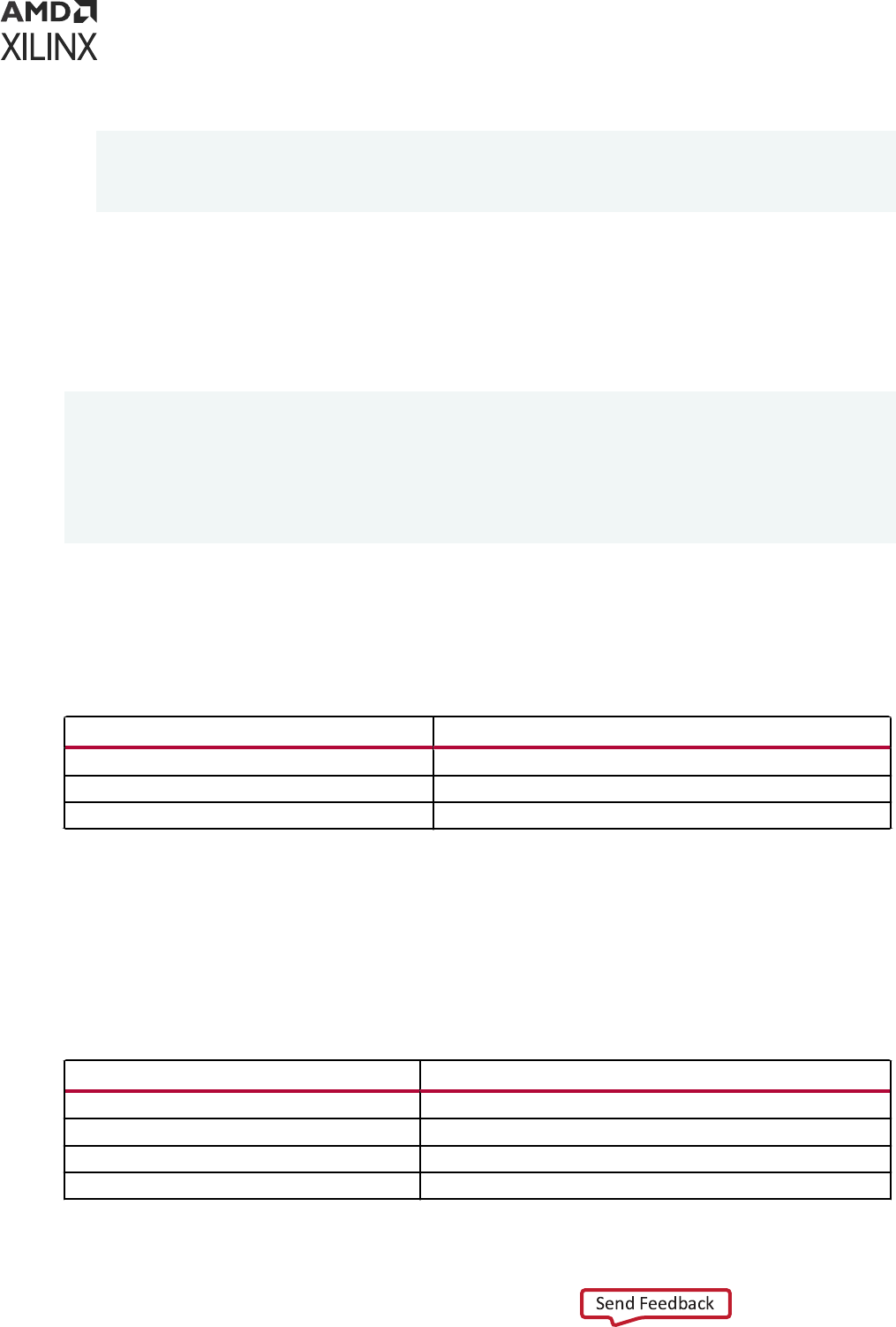
2. Use named or posional associaon to instanate the Verilog module. For example:
UUT : MY_VHDL_UNIT PORT MAP(
Q => O,
D => I,
C => CLK);
Instantiating a VHDL Component in a Verilog/SV Design Unit
To instanate a VHDL component in a Verilog/SV design unit, instanate the VHDL component
as if it were a Verilog/SV module.
For example:
module testbench ;
wire in, clk;
wire out;
FD FD1(
.Q(Q_OUT),
.C(CLK);
.D(A);
);
Port Mapping and Supported Port Types
The following table lists the supported port types.
Table 49: Supported Port Types
VHDL
1
Verilog/SV
2
IN INPUT
OUT OUTPUT
INOUT INOUT
Notes:
1. Buffer and linkage ports of VHDL are not supported.
2. Connection to bi-directional pass switches in Verilog are not supported. Unnamed Verilog ports are not allowed on
mixed design boundary.
The following table shows the supported VHDL and Verilog data types for ports on the mixed
language design boundary.
Table 50: Supported VHDL and Verilog Data Types
VHDL Port Verilog Port
bit
net
std_logic
net
bit_vector
vector net
signed
vector net
Appendix J: Vivado Simulator Mixed Language Support and Language Exceptions
UG900 (v2022.1) April 21, 2022 www.xilinx.com
Vivado Design Suite User Guide: Logic Simulation 246

Table 50: Supported VHDL and Verilog Data Types (cont'd)
VHDL Port Verilog Port
unsigned
vector net
std_ulogic_vector
vector net
std_logic_vector
vector net
Note: Verilog output port of type reg is supported on the mixed language boundary. On the boundary, an
output reg port is treated as if it were an output net (wire) port. Any other type found on mixed language
boundary is considered an error.
Note: The Vivado simulator supports the record element as an actual in the port map of a Verilog module
that is instanated in the mixed domain. All those types that are supported as VHDL port (listed in Table
50: Supported VHDL and Verilog Data Types) are also supported as a record element.
Table 51: Supported SV and VHDL Data Types
SV Data type VHDL Data type
Int
bit_vector
std_logic_Vector
std_ulogic_vector
signed
unsigned
byte
bit_vector
std_logic_Vector
std_ulogic_vector
signed
unsigned
shortint
bit_vector
std_logic_Vector
std_ulogic_vector
signed
unsigned
longint
bit_vector
std_logic_Vector
std_ulogic_vector
signed
unsigned
integer
bit_vector
Appendix J: Vivado Simulator Mixed Language Support and Language Exceptions
UG900 (v2022.1) April 21, 2022 www.xilinx.com
Vivado Design Suite User Guide: Logic Simulation 247

Table 51: Supported SV and VHDL Data Types (cont'd)
SV Data type VHDL Data type
std_logic_Vector
std_ulogic_vector
signed
unsigned
vector of bit(1D)
bit_vector
std_logic_Vector
std_ulogic_vector
signed
unsigned
vector of logic(1D)
bit_vector
std_logic_Vector
std_ulogic_vector
signed
unsigned
vector of reg(1D)
bit_vector
std_logic_Vector
std_ulogic_vector
signed
unsigned
logic/bit
bit
std_logic
std_ulogic
bit_vector
std_logic_Vector
std_ulogic_vector
signed
unsigned
Note: VHDL enty instanang Verilog Module having real port is supported.
Generics (Parameters) Mapping
The Vivado simulator supports the following VHDL generic types (and their Verilog/SV
equivalents):
Appendix J: Vivado Simulator Mixed Language Support and Language Exceptions
UG900 (v2022.1) April 21, 2022 www.xilinx.com
Vivado Design Suite User Guide: Logic Simulation 248
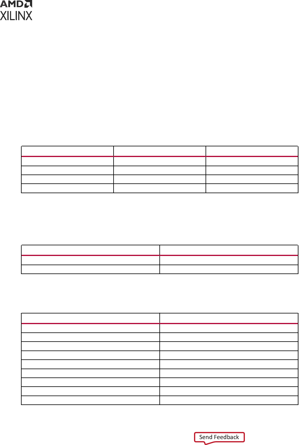
• integer
• real
• string
• boolean
Note: Any other generic type found on mixed language boundary is considered an error.
VHDL and Verilog Values Mapping
The following table lists the Verilog states mappings to std_logic and bit.
Table 52: Verilog States Mapped to std_logic and bit
Verilog std_logic bit
Z Z 0
0 0 0
1 1 1
X X 0
Note: Verilog strength is ignored. There is no corresponding mapping to strength in VHDL.
The following table lists the VHDL type bit mapping to Verilog states.
Table 53: VHDL bit Mapping to Verilog States
bit Verilog
0 0
1 1
The folowing table lists the VHDL type std_logic mappings to Verilog states.
Table 54: VHDL std_logic Mapping to Verilog States
std_logic Verilog
U X
X X
0 0
1 1
Z Z
W X
L 0
H 1
- X
Appendix J: Vivado Simulator Mixed Language Support and Language Exceptions
UG900 (v2022.1) April 21, 2022 www.xilinx.com
Vivado Design Suite User Guide: Logic Simulation 249

Because Verilog is case sensive, named associaons and the local port names that you use in
the component declaraon must match the case of the corresponding Verilog port names.
VHDL Language Support Exceptions
Certain language constructs are not supported by the Vivado simulator. The following table lists
the VHDL language support excepons.
Table 55: VHDL Language Support Exceptions
Supported VHDL Construct Exceptions
abstract_literal
Floating point expressed as based literals are not supported.
alias_declaration
Alias to non-objects are in general not supported;
particularly the following:
• Alias of an alias
• Alias declaration without subtype_indication
• Signature on alias declarations
• Operator symbol as alias_designator
• Alias of an operator symbol
• Character literals as alias designators
alias_designator
Operator_symbol as alias_designator
Character_literal as alias_designator
association_element
Globally, locally static range is acceptable for taking slice of
an actual in an association element.
attribute_name
Signature after prefix is not supported.
binding_indication
Binding_indication without use of entity_aspect is not
supported.
bit_string_literal
Empty bit_string_literal (" ") is not supported.
block_statement
Guard_expression is not supported; for example, guarded
blocks, guarded signals, guarded targets, and guarded
assignments are not supported.
choice
Aggregate used as choice in case statement is not
supported.
concurrent_assertion_statement
Postponed is not supported.
concurrent_signal_assignment_statement
Postponed is not supported.
concurrent_statement
Concurrent procedure call containing wait statement is not
supported.
conditional_signal_assignment
Keyword guarded as part of options is not supported as
there is no supported for guarded signal assignment.
configuration_declaration
Non locally static for generate index used in configuration is
not supported.
entity_class
Literals, unit, file, and group as entity class are not
supported.
Appendix J: Vivado Simulator Mixed Language Support and Language Exceptions
UG900 (v2022.1) April 21, 2022 www.xilinx.com
Vivado Design Suite User Guide: Logic Simulation 250

Table 55: VHDL Language Support Exceptions (cont'd)
Supported VHDL Construct Exceptions
entity_class_entry
Optional <> intended for use with group templates is not
supported.
file_logical_name
Although file_logical_name is allowed to be any wild
expression evaluating to a string value, only string literal and
identifier is acceptable as file name.
function_call
Slicing, indexing, and selection of formals is not supported in
a named parameter association within a function_call.
instantiated_unit
Direct configuration instantiation is not supported.
mode
Linkage and Buffer ports are not supported completely.
options
Guarded is not supported.
primary
At places where primary is used, allocator is expanded there.
procedure_call
Slicing, indexing, and selection of formals is not supported in
a named parameter association within a procedure_call.
process_statement
Postponed processes are not supported.
selected_signal_assignment
The guarded keyword as part of options is not supported as
there is no support for guarded signal assignment.
signal_declaration
The signal_kind is not supported. The signal_kind is
used for declaring guarded signals, which are not supported.
subtype_indication
Resolved subtype of composites (arrays and records) is not
supported.
waveform
Unaffected is not supported.
waveform_element
Null waveform element is not supported as it only has
relevance in the context of guarded signals.
Verilog Language Support Exceptions
The following table lists the excepons to supported Verilog language support.
Table 56: Verilog Language Support Exceptions
Verilog Construct Exception
Compiler Directive Constructs
`unconnected_drive
not supported
`nounconnected_drive
not supported
Attributes
attribute_instance
not supported
attr_spec
not supported
attr_name
not supported
Primitive Gate and Switch Types
cmos_switchtype
not supported
mos_switchtype
not supported
Appendix J: Vivado Simulator Mixed Language Support and Language Exceptions
UG900 (v2022.1) April 21, 2022 www.xilinx.com
Vivado Design Suite User Guide: Logic Simulation 251

Table 56: Verilog Language Support Exceptions (cont'd)
Verilog Construct Exception
pass_en_switchtype
not supported
Generated Instantiation
generated_instantiation
The module_or_generate_item alternative is not supported.
Production from IEEE standard (see IEEE Standard Verilog Hardware
Description Language (IEEE-STD-1364-2001) section 13.2 ):
generate_item_or_null ::=
generate_conditonal_statement |
generate_case_statement |
generate_loop_statement |
generate_block |
module_or_generate_item
Production supported by Simulator:
generate_item_or_null ::=
generate_conditional_statement|
generate_case_statement |
generate_loop_statement |
generate_blockgenerate_condition
genvar_assignment
Partially supported.
All generate blocks must be named.
Production from standard (see IEEE Standard Verilog Hardware
Description Language (IEEE-STD-1364-2001) section 13.2):
generate_block ::=
begin
[ : generate_block_identifier ]
{ generate_item }
end
Production supported by Simulator:
generate_block ::=
begin:
generate_block_identifier {
generate_item }
end
Source Text Constructs
Library Source Text
library_text
not supported
library_descriptions
not supported
library_declaration
not supported
include_statement
This refers to include statements within library map files (See IEEE
Standard Verilog Hardware Description Language (IEEE-STD-1364-2001)
section 13.2. This does not refer to the `include compiler directive.
System Timing Check Commands
$skew_timing_check
not supported
$timeskew_timing_check
not supported
$fullskew_timing_check
not supported
Appendix J: Vivado Simulator Mixed Language Support and Language Exceptions
UG900 (v2022.1) April 21, 2022 www.xilinx.com
Vivado Design Suite User Guide: Logic Simulation 252

Table 56: Verilog Language Support Exceptions (cont'd)
Verilog Construct Exception
$nochange_timing_check
not supported
System Timing Check Command Argument
checktime_condition
not supported
PLA Modeling Tasks
$async$nand$array
not supported
$async$nor$array
not supported
$async$or$array
not supported
$sync$and$array
not supported
$sync$nand$array
not supported
$sync$nor$array
not supported
$sync$or$array
not supported
$async$and$plane
not supported
$async$nand$plane
not supported
$async$nor$plane
not supported
$async$or$plane
not supported
$sync$and$plane
not supported
$sync$nand$plane
not supported
$sync$nor$plane
not supported
$sync$or$plane
not supported
Value Change Dump (VCD) Files
$dumpportson
$dumpports
$dumpportsoff
$dumpportsflush
$dumpportslimit
$vcdplus
not supported
Appendix J: Vivado Simulator Mixed Language Support and Language Exceptions
UG900 (v2022.1) April 21, 2022 www.xilinx.com
Vivado Design Suite User Guide: Logic Simulation 253

Appendix K
Vivado Simulator Quick Reference
Guide
The following table provides a quick reference and examples for common Vivado
®
simulator
commands.
Parsing HDL Files
Vivado simulator supports three HDL file types: Verilog, SystemVerilog and VHDL. You can parse the supported files using
XVHDL and XVLOG commands.
Parsing VHDL files
xvhdl file1.vhd file2.vhd
xvhdl -work worklib file1.vhd file2.vhd
xvhdl -prj files.prj
Parsing Verilog
files
xvlog file1.v file2.v
xvlog -work worklib file1.v file2.v
xvlog -prj files.prj
Parsing
SystemVerilog
files
xvlog -sv file1.v file2.v
xvlog -work worklib -sv file1.v file2.v
xvlog -prj files.prj
For information about the PRJ file format, see Project File (.prj) Syntax.
Additional xvlog and xvhdl Options
xvlog and xvhdl
Key Options
See Table 15: xelab, xvhd, and xvlog Command Options for a complete list of command options.
The following are key options for xvlog and xvhdl:
Key Option Applies to:
xelab, xvhdl, and xvlog xsim
Command Options
xvlog
xelab, xvhdl, and xvlog xsim
Command Options
xvlog, xvhdl
xelab, xvhdl, and xvlog xsim
Command Options
xvlog
xelab, xvhdl, and xvlog xsim
Command Options
xvlog, xvhdl
xelab, xvhdl, and xvlog xsim
Command Options
xvlog, xvhdl
xelab, xvhdl, and xvlog xsim
Command Options
xvlog, xvhdl
xelab, xvhdl, and xvlog xsim
Command Options
xvlog, xvhdl
xelab, xvhdl, and xvlog xsim
Command Options
xvhdl, vlog
xelab, xvhdl, and xvlog xsim
Command Options
xvlog, xvhdl
Appendix K: Vivado Simulator Quick Reference Guide
UG900 (v2022.1) April 21, 2022 www.xilinx.com
Vivado Design Suite User Guide: Logic Simulation 254
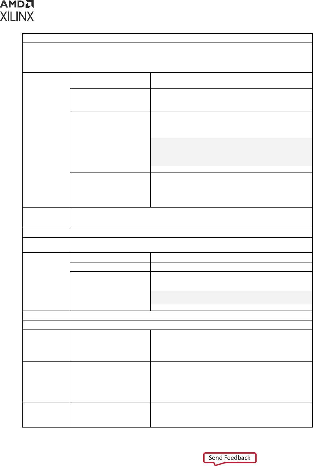
Elaborating and Generating an Executable Snapshot
After parsing, you can elaborate the design in Vivado simulator using the XELAB command. XELAB generates an
executable snapshot.
You can skip the parser stage, directly invoke the XELAB command, and pass the PRJ file. XELAB calls XVLOG and XVHDL for
parsing the files.
Usage
xelab top1 top2
Elaborates a design that has two top design units: top1 and top2.
In this example, the design units are compiled in the work library.
xelab lib1.top1 lib2.top2
Elaborates a design that has two top design units: top1 and top2.
In this example, the design units have are compiled in lib1 and
lib2, respectively
xelab top1 top2 -prj
files.prj
Elaborates a design that has two top design units: top1 and top2.
In this example, the design units are compiled in the work library.
The file files.prj contains entries such as:
verilog <libraryName>
<VerilogDesignFileName>
vhdl <libraryName> <VHDLDesignFileName>
sv <libraryName>
<SystemVerilogDesignFileName>
xelab top1 top2 -s top
Elaborates a design that has two top design units: top1 and top2.
In this example, the design units are compiled in the work library.
After compilation, xelab generates an executable snapshot with
the name top. Without the -s top switch, xelab creates the
snapshot by concatenating the unit names.
Command Line
Help and xelab
Options
xelab -help
Table 15: xelab, xvhd, and xvlog Command Options
Running Simulation
After parsing, elaboration and compilation stages are successful; xsim generates an executable snapshot to run
simulation.
Usage
xsim top -R
Simulates the design to through completion.
xsim top -gui
Opens the Vivado simulator workspace (GUI).
xsim top
Opens the Vivado Design Suite command prompt in Tcl mode.
From there, you can invoke such options as:
run -all
run 100 ns
Important Shortcuts
You can invoke the parsing, elaboration, and executable generation and simulation in one, two, or three stages.
Three Stage
xvlog bot.v
xvhdl top.vhd
xelab work.top -s top
xsim top -R
Two Stage
xelab -prj my_prj.prj work.top -s top
xsim top -R
where my_prj.prj file contains:
verilog work bot.v
vhdl work top.vhd
Single Stage
xelab -prj my_prj.prj work.top -s top -R
where my_prj.prj file contains:
verilog work bot.v vhdl work top.vhd
Appendix K: Vivado Simulator Quick Reference Guide
UG900 (v2022.1) April 21, 2022 www.xilinx.com
Vivado Design Suite User Guide: Logic Simulation 255

Note: If your design contain UVM construct then you need to pass -L uvm to xvlog and xelab command
Vivado Simulation Tcl Commands
The following are commonly used Tcl commands. For a complete list, invoke following commands in the Tcl Console:
load_features simulator
help -category simulation
For information on any Tcl Command, type: -help <Tcl_command>
Common Vivado
Simulator Tcl
Commands:
add_bp
Add break point at a line of HDL source.
add_force
Force the value of a signal, wire, or register to a specified value. Tcl
command exampled are provided on Using Force Commands.
current_time
now
Report current simulation time. See Using a -tclbatch File for an
example of this command within a Tcl script.
current_scope
Report or set the current, working HDL scope. See Scope Window
for more information.
get_objects
Get a list of HDL objects in one or more HDL scopes, per the
specified pattern. For example command usage refer to: Example
SAIF Tcl Commands.
get_scopes
Get a list of child HDL scopes. See Scope Window for more
information.
get_value
Get the current value of the selected HDL object (variable, signal,
wire, register). Type get_value -help in Tcl Console for more
information.
launch_simulation
Launch simulation using the Vivado simulator.
remove_bps
Remove breakpoints from a simulation.
report_drivers
Print drivers along with current driving values for an HDL wire or
signal object. Reference for more information: Using the
report_drivers Tcl Command.
report_values
Print current simulated value of given HDL objects (variables,
signals, wires, or registers). For example Tcl command usage, see
Scope Window.
restart
Rewind simulation to post loading state (as though the design was
reloaded); time is set to 0.
set_value
Set the HDL object (variable, signal, wire, or register) to a specified
value. Reference for more information: Appendix I: Value Rules in
Vivado Simulator Tcl Commands.
step
Step simulation to the next statement. See Stepping Through a
Simulation.
Appendix K: Vivado Simulator Quick Reference Guide
UG900 (v2022.1) April 21, 2022 www.xilinx.com
Vivado Design Suite User Guide: Logic Simulation 256

Appendix L
Using Xilinx Simulator Interface
The Xilinx
®
Simulator Interface (XSI) is a C/C++ applicaon programming interface (API) to the
Xilinx Vivado simulator (xsim) that enables a C/C++ program to serve as the test bench for a HDL
design. Using XSI, the C/C++ program controls the acvity of the Vivado simulator which hosts
the HDL design.
The C/C++ program controls the simulaon in the following methods:
• Seng the values of the top-level input ports of the HDL design
• Instrucng the Vivado simulator to run the simulaon for a certain amount of simulaon me
Addionally, the C/C++ program can read the values of the top-level output ports of the HDL
design.
Perform the following steps to use XSI in your C/C++ program:
1. Prepare the XSI API funcons to be called through dynamic linking
2. Write your C/C++ test bench code using the API funcons
3. Compile and link your C/C++ program
4. Package the Vivado simulator and the HDL design together into a shared library
Preparing the XSI Functions for Dynamic
Linking
Xilinx recommends the usage of dynamic linking for indirectly calling the XSI funcons. While
this technique involves more steps than simply calling XSI funcons directly, dynamic linking
allows you to keep the compilaon of your HDL design independent of the compilaon of your
C/C++ program. You can compile and load your HDL design at any me, even while your C/C++
program connues to run.
To call a funcon through dynamic linking requires your program to perform the following steps:
1. Open the shared library containing the funcon.
2. Look up the funcon by name to get a pointer to the funcon.
Appendix L: Using Xilinx Simulator Interface
UG900 (v2022.1) April 21, 2022 www.xilinx.com
Vivado Design Suite User Guide: Logic Simulation 257
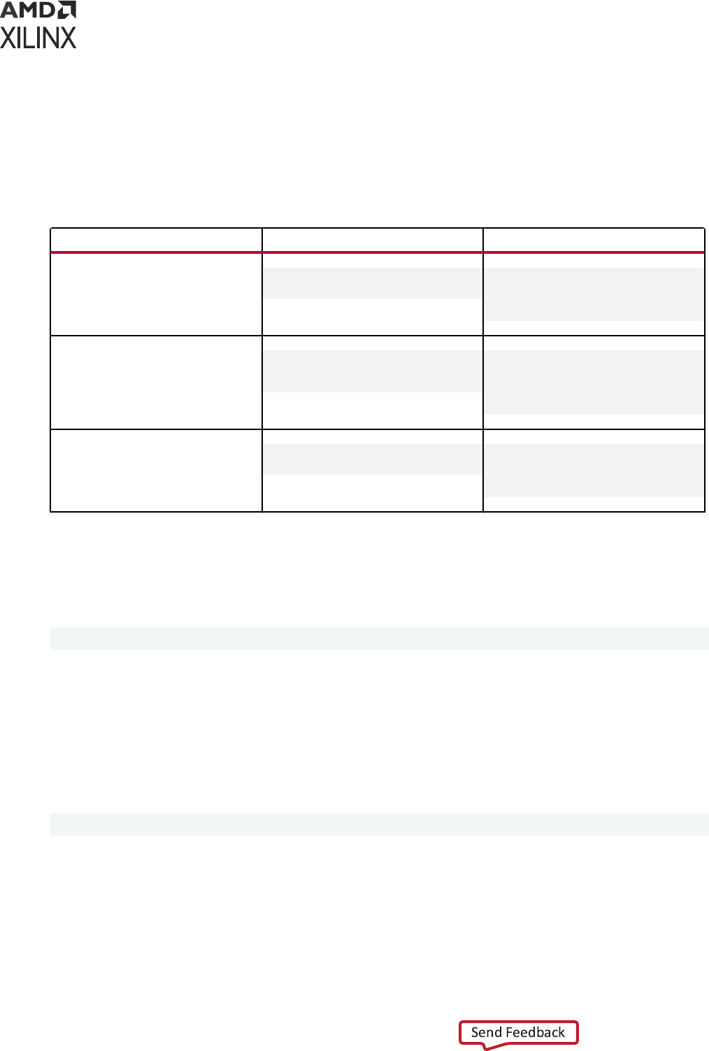
3. Call the funcon using the funcon pointer.
4. Close the shared library (oponal).
Steps 1, 2, and 4 require the use of OS-specic library calls, as shown in the following table. See
your operang system documentaon for details about these funcons.
Table 58: Operating System Specific Library Calls
Function Linux Windows
Open shared library
void *dlopen(const char
*filename, int flag);
HMODULE WINAPI
LoadLibrary(_In_ LPCTSTR
lpFileName
);
Look up function by name
void *dlsym(void
*handle, const char
*symbol);
FARPROC WINAPI
GetProcAddress(_In_
HMODULE hModule,_In_
LPCSTR lpProcName
);
Close shared library
int dlclose(void
*handle);
BOOL WINAPI
FreeLibrary(_In_ HMODULE
hModule
);
XSI requires you to call funcons from two shared libraries: the kernel shared library and your
design shared library. The kernel shared library ships with the Vivado simulator and is called
librdi_simulator_kernel.so (Linux) or librdi_simulator_kernel.dll (Windows).
It resides in the following directory:
<Vivado Installation Root>/lib/<platform>
where <platform> is lnx64.o or win64.o. Make sure to include this directory in your library
path while running your program. On Linux, include the directory in the environment variable
LD_LIBRARY_PATH, and on Windows, in the environment variable PATH.
Your design shared library, which the Vivado simulator creates in the course of compiling your
HDL design, as described in Preparing the Design Shared Library, is called xsimk.so (Linux) or
xsimk.dll (Windows) and typically resides at the following locaon:
<HDL design directory>/xsim.dir/<snapshot name>
where <HDL design directory> is the directory from which your design shared library was
created, and <snapshot name> is the name of the snapshot that you specify during the
creaon of the library.
Your C/C++ program will call the XSI funcon xsi_open() residing in your design shared library
and all other XSI funcons from the kernel shared library.
Appendix L: Using Xilinx Simulator Interface
UG900 (v2022.1) April 21, 2022 www.xilinx.com
Vivado Design Suite User Guide: Logic Simulation 258
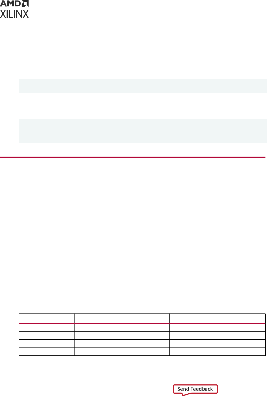
The XSI code examples that ship with the Vivado simulator consolidate the XSI funcons into a C
++ class called Xsi::Loader. The class accepts the names of the two shared libraries, internally
executes the necessary dynamic linking steps, and exposes all the XSI funcons as member
funcons of the class. Wrapping the XSI funcons in this manner eliminates the necessity of
calling the dynamic linking OS funcons directly. You can nd the source code for the class that
can be copied into your own program at the following locaon under your Vivado installaon:
<Vivado Installation Root>/examples/xsim/verilog/xsi/counter/xsi_loader.h
<Vivado Installation Root>/examples/xsim/verilog/xsi/counter/xsi_loader.cpp
To use Xsi::Loader, simply instanate it by passing the names of the two shared libraries as
shown in the following example:
#include "xsi_loader.h"
...
Xsi::Loader loader("xsim.dir/mySnapshot/xsimk.so",
"librdi_simulator_kernel.so");
Writing the Test Bench Code
A C/C++ test bench using XSI typically uses the following steps:
1. Open the design.
2. Fetch the IDs of each top-level port.
3. Repeat the following unl the simulaon is nished:
a. Set values on top-level input ports.
b. Run the simulaon for a specic amount of me.
c. Fetch the values of top-level output ports.
4. Close the design.
The following table lists the XSI funcons and their Xsi::Loader member funcon equivalents
to use for each step. You can nd the usage details for each XSI funcon in the XSI Funcon
Reference.
Table 59: Xsi: :Loader Member Functions
Activity XSI Function
Xsi::Loader Member Function
Open the design
xsi_open open
Fetch a port ID
xsi_get_port_number get_port_number
Set an input port value
xsi_put_value put_value
Run the simulation
xsi_run run
Appendix L: Using Xilinx Simulator Interface
UG900 (v2022.1) April 21, 2022 www.xilinx.com
Vivado Design Suite User Guide: Logic Simulation 259
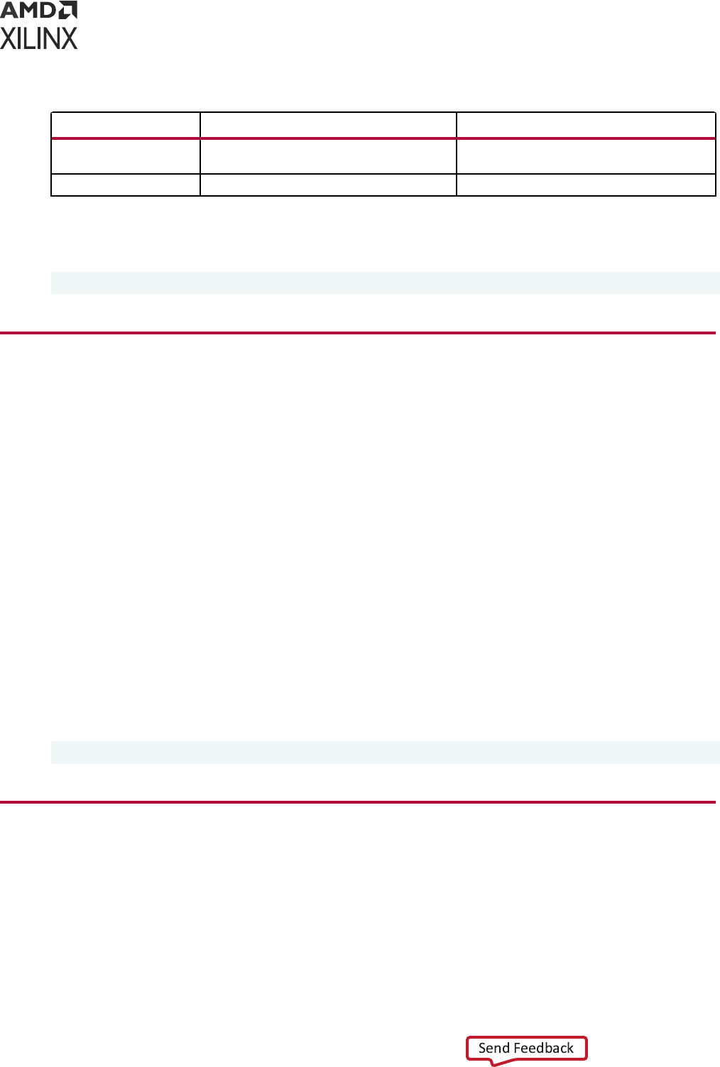
Table 59: Xsi: :Loader Member Functions (cont'd)
Activity XSI Function
Xsi::Loader Member Function
Fetch an output port
value
xsi_get_value get_value
Close the design
xsi_close close
You can nd the example C++ programs that use XSI in your Vivado simulator installaon at the
following locaon:
<Vivado Installation Root>/examples/xsim/<HDL language>/xsi
Compiling Your C/C++ Program
You can use the XSI example programs as a guideline. Each example supplies one or two scripts
for compiling and running the example. Refer to your compiler's documentaon for details on
compiling a program. On Linux, compiling and running is a two-step process.
1. In a C shell, source set_env.csh
2. Invoke run.csh
On Windows, simply run the batch le run.bat.
Note the following from the scripts:
1. The compilaon lines specify (via -I) the inclusion of the directory containing the xsi.h
include le.
2. There is no menon of the design shared library or kernel shared library during the
compilaon of a C++ program.
The XSI include le resides at the following locaon:
<Vivado Installation Root>/data/xsim/include/xsi.h
Preparing the Design Shared Library
The last step for producing a working XSI-based C/C++ program involves the compilaon of a
HDL design and packaging it together with the Vivado simulator to become your design shared
library. You may repeat this step whenever there is a change in HDL designs source code.
Appendix L: Using Xilinx Simulator Interface
UG900 (v2022.1) April 21, 2022 www.xilinx.com
Vivado Design Suite User Guide: Logic Simulation 260
CAUTION! If you intend to rebuild the design shared library for your C/C++ program while your program
connues to run, be sure to close the design in your program before execung this step.
Create your design shared library by invoking xelab on the HDL design and including the -dll
switch to instruct xelab to produce a shared library instead of the usual snapshot for use with the
Vivado simulator's user interface.
For example:
Type the following in the Linux command line to create a design shared library at ./xsim.dir/
design/xsimk.so:
xelab work.top1 work.top2 -dll -s design
where work.top1 and work.top2 are the top module names and design is the snapshot
name.
See xelab, xvhdl, and xvlog xsim Command Opons for more details on compiling an HDL design.
XSI Function Reference
This secon presents each of the XSI API funcons in plain (direct C call) and Xsi::Loader
member funcon forms. The plain form funcons take an xsiHandle argument, whereas the
member funcons do not take this argument. The xsiHandle contains state informaon about
the opened HDL design. The plain form xsi_open produces the xsiHandle. Xsi::Loader
contains an xsiHandle internally.
xsi_close
void xsi_close(xsiHandle design_handle);
void Xsi::Loader::close();
This funcon closes an HDL design, freeing the memory associated with the design. Call this
funcon to end the simulaon.
xsi_get_error_info
const char* xsi_get_error_info(xsiHandle design_handle);
const char* Xsi::Loader::get_error_info();
This funcon returns a string descripon of the last error encountered.
Appendix L: Using Xilinx Simulator Interface
UG900 (v2022.1) April 21, 2022 www.xilinx.com
Vivado Design Suite User Guide: Logic Simulation 261
xsi_get_port_number
XSI_INT32 xsi_get_port_number(xsiHandle design_handle, const char*
port_name);
int Xsi::Loader::get_port_number(const char* port_name);
This funcon returns an integer ID for the requested top-level port of the HDL design. You may
subsequently use the ID to specify the port in xsi_get_value and xsi_put_value calls.
port_name is the name of the port and is case sensive for Verilog and case insensive for
VHDL. The funcon returns -1 if no port of the specied name exists.
Example code:
#include "xsi.h"
#include "xsi_loader.h"
...
Xsi::Loader loader("xsim.dir/mySnapshot/
xsimk.so","librdi_simulator_kernel.so");
...
int count = loader.get_port_number("count");
xsi_get_status
XSI_INT32 xsi_get_status(xsiHandle design_handle);
int Xsi::Loader::get_status();
This funcon returns the status of the simulaon. The status may be equal to one of the
following ideners:
Table 60: Xsi Simulation Status Identifiers
Status Code Identifiers Description
xsiNormal
No error
xsiError
The simulation has encountered an HDL run-time error
xsiFatalError
The simulation has encountered an error condition for which the
Vivado simulator cannot continue.
Example code:
#include "xsi.h"
#include "xsi_loader.h"
...
Xsi::Loader loader("xsim.dir/mySnapshot/
xsimk.so","librdi_simulator_kernel.so");
...
if (loader.get_status() == xsiError)
printf("HDL run-time error encountered.\n");
Appendix L: Using Xilinx Simulator Interface
UG900 (v2022.1) April 21, 2022 www.xilinx.com
Vivado Design Suite User Guide: Logic Simulation 262

xsi_get_value
void xsi_get_value(xsiHandle design_handle, XSI_INT32 port_number, void*
value);
int Xsi::Loader::get_value(int port_number, void* value);
This funcon fetches the value of the port indicated by port ID port_number. The value is
placed in the memory buer to which value points. See xsi_get_port_number for informaon on
obtaining an ID for a port.
IMPORTANT! Your program must allocate sucient memory for the buer before calling the funcon.
See Vivado Simulator VHDL Data Format and Vivado Simulator Verilog Data Format to determine the
necessary size of the buer.
Example code:
#include "xsi.h"
#include "xsi_loader.h"
...
// Buffer for value of port "count"
s_xsi_vlog_logicval count_val = {0X00000000, 0X00000000};
Xsi::Loader loader("xsim.dir/mySnapshot/
xsimk.so","librdi_simulator_kernel.so");
...
int count = loader.get_port_number("count");
loader.get_value(count, &count_val);
xsi_open
typedef struct t_xsi_setup_info {
char* logFileName;
char* wdbFileName;
} s_xsi_setup_info, *p_xsi_setup_info;
xsiHandle xsi_open(p_xsi_setup_info setup_info);
void Xsi::Loader::open(p_xsi_setup_info setup_info);
bool Xsi::Loader::isopen() const;
This funcon opens an HDL design for simulaon. To use this funcon, you must rst inialize an
s_xsi_setup_info struct to pass to the funcon. Use logFileName for the name of the
simulaon log le, or NULL to disable logging. If waveform tracing is on (see xsi_trace_all),
wdbFileName is the name of the output WDB (waveform database) le. Use NULL for the
default name of xsim.wdb. If the waveform tracing is o, the Vivado simulator ignores the
wdbFileName eld.
TIP:
To protect your program from future changes to the XSI API, Xilinx recommends that you zero out the
s_xsi_setup_info
struct before lling in the elds, as shown in the xsi_open.
Appendix L: Using Xilinx Simulator Interface
UG900 (v2022.1) April 21, 2022 www.xilinx.com
Vivado Design Suite User Guide: Logic Simulation 263
The plain (non-loader) form of the funcon returns an xsiHandle, a C object containing process
state informaon about the design, to be used with all other plain-form XSI funcons. The loader
form of the funcon has no return value. However, you may check whether the loader has
opened a design by querying the isopen member funcon, which returns true if the open
member funcon had been invoked.
Example
#include "xsi.h"
#include "xsi_loader.h"
...
Xsi::Loader loader("xsim.dir/mySnapshot/
xsimk.so","librdi_simulator_kernel.so");
s_xsi_setup_info info;
memset(&info, 0, sizeof(info));
info.logFileName = NULL;
char wdbName[] = "test.wdb"; // make a buffer for holding the string
"test.wdb"
info.wdbFileName = wdbName;
loader.open(&info);
xsi_put_value
void xsi_put_value(xsiHandle design_handle, XSI_INT32 port_number, void*
value);
void Xsi::Loader::put_value(int port_number, const void* value);
This funcon deposits the value stored in value onto the port specied by port ID
port_number. See xsi_get_port_number for informaon on obtaining an ID for a port. value is
a pointer to a memory buer that your program must allocate and ll. See the Vivado Simulator
VHDL Data Format and Vivado Simulator Verilog Data Format for informaon on the proper
format of value.
CAUTION!
For maximum performance, the Vivado simulator performs no checking on the size or type of
the value you pass to
xsi_put_value
. Passing a value to
xsi_put_value
which does not match
the size and type of the port may result in unpredictable behavior of your program and the Vivado
simulator.
Example code:
#include "xsi.h"
#include "xsi_loader.h"
...
// Hard-coded Buffer for a 1-bit "1" Verilog 4-state value
const s_xsi_vlog_logicval one_val = {0X00000001, 0X00000000};
Xsi::Loader loader("xsim.dir/mySnapshot/
xsimk.so","librdi_simulator_kernel.so");
...
int clk = loader.get_port_number("clk");
loader.put_value(clk, &one_val); // set clk to 1
Appendix L: Using Xilinx Simulator Interface
UG900 (v2022.1) April 21, 2022 www.xilinx.com
Vivado Design Suite User Guide: Logic Simulation 264

xsi_restart
void xsi_restart(xsiHandle design_handle);
void Xsi::Loader:: restart();
This funcon resets the simulaon to simulaon me 0.
xsi_run
void xsi_run(xsiHandle design_handle, XSI_UINT64 time_ticks);
void Xsi::Loader::run(XSI_INT64 step);
This funcon runs the simulaon for the given amount of me specied in kernel precision units.
A kernel precision unit is the smallest unit of me precision specied among all HDL source les
of the design. For example, if a design has two source les, one of which that species a
precision of 1 ns and the other species a precision of 1 ps, the kernel precision unit becomes 1
ps, as that me unit is the smaller of the two.
A Verilog source le may specify the me precision using the `timescale direcve.
Example:
`timescale 1ns/1ps
In this example, the me unit aer the / (1 ps) is the me precision. VHDL has no equivalent of
`timescale.
You may addionally adjust the kernel precision unit through the use of the xelab command-
line opons --timescale, --override_timeprecision, and --timeprecision_vhdl.
See xelab, xvhdl, and xvlog xsim Command Opons for informaon on the use of these
command-line opons.
Note: xsi_run blocks unl the specied simulaon run me has elapsed. Your program and the Vivado
simulator share a single thread of execuon.
xsi_trace_all
void xsi_trace_all(xsiHandle design_handle);
void Xsi::Loader:: trace_all();
Call this funcon aer xsi_open to turn on waveform tracing for all signals of the HDL design.
Running the simulaon with waveform tracing on causes the Vivado simulator to produce a
waveform database (WDB) le containing all events for every signal in the design. The default
name of the WDB le is xsim.wdb. To specify a dierent WDB le name, set the
wdbFileName eld of the s_xsi_setup_info struct when calling xsi_open, as shown in
the example code.
Appendix L: Using Xilinx Simulator Interface
UG900 (v2022.1) April 21, 2022 www.xilinx.com
Vivado Design Suite User Guide: Logic Simulation 265

Example code:
#include "xsi.h"
#include "xsi_loader.h"
...
Xsi::Loader loader("xsim.dir/mySnapshot/
xsimk.so","librdi_simulator_kernel.so");
s_xsi_setup_info info;
memset(&info, 0, sizeof(info));
char wdbName[] = "test.wdb"; // make a buffer for holding the string
"test.wdb"
info.wdbFileName = wdbName;
loader.open(&info);
loader.trace_all();
Aer the simulaon completes, you can open the WDB le in Vivado to examine the waveforms
of the signals. See Opening a Previously Saved Simulaon Run for more informaon on how to
view WDB les in Vivado.
IMPORTANT! When compiling the HDL design, you must specify
-debug all
or
-debug typical
on the xelab command line. The Vivado simulator will not record the waveform data without the
-debug
command line opon.
Vivado Simulator VHDL Data Format
This secon describes how to convert between VHDL values and the format of the memory
buers to use with the XSI funcons xsi_get_value and xsi_put_value.
IEEE std_logic Type
A single bit of VHDL std_logic and std_ulogic is represented in C/C++ as a single byte
(char or unsigned char). The following table shows the values of std_logic/std_ulogic and
their C/C++ equivalents.
Table 61: std_logic/std_ulogic Values and their C/C++ Equivalents
std_logic Value
C/C++ Byte Value (Decimal)
'U‘
0
‘X‘
1
‘0‘
2
‘1‘
3
‘Z‘
4
‘W‘
5
‘L‘
6
‘H‘
7
Appendix L: Using Xilinx Simulator Interface
UG900 (v2022.1) April 21, 2022 www.xilinx.com
Vivado Design Suite User Guide: Logic Simulation 266
Table 61: std_logic/std_ulogic Values and their C/C++ Equivalents (cont'd)
std_logic Value
C/C++ Byte Value (Decimal)
‘_‘
8
Example code:
// Put a '1' on signal "clk," where "clk" is defined as
// signal clk : std_logic;
const char one_val = 3; // C encoding for std_logic '1'...
int clk = loader.get_port_number("clk");
loader.put_value(clk, &one_val); // set clk to 1
VHDL bit Type
A single bit of VHDL bit type is represented in C/C++ as a single byte. The following table
shows the values of bit and their C/C++ equivalents.
Table 62: Values of bit and their C/C++ equivalents
bit Value
C/C++ Byte Value (Decimal)
'0‘
0
‘1‘
1
Example code:
// Put a '1' on signal "clk," where "clk" is defined as
// signal clk : bit;
const char one_val = 1; // C encoding for bit '1'...
int clk = loader.get_port_number("clk");
loader.put_value(clk, &one_val); // set clk to 1
VHDL Character Type
A single VHDL character value is represented in C/C++ as a single byte. VHDL character
values are exactly idencal to C/C++ char literals and are also equal to their ASCII numeric
values. For example, the VHDL character value 'm’ is equivalent to the C/C++ char literal 'm’ or
decimal value 109.
Example code:
// Put a 'T' on signal "myChar," where "myChar" is defined as
// signal myChar : character;
const char tVal = 'T';
int myChar = loader.get_port_number("myChar");
loader.put_value(myChar, &tVal);
Appendix L: Using Xilinx Simulator Interface
UG900 (v2022.1) April 21, 2022 www.xilinx.com
Vivado Design Suite User Guide: Logic Simulation 267
VHDL integer Type
A single VHDL integer value is represented in C/C++ as an int.
Example code:
// Put 1234 (decimal) on signal "myInt," where "myInt" is defined as
// signal myInt : integer;
const int intVal = 1234;
int myInt = loader.get_port_number("myInt");
loader.put_value(myInt, &intVal);
VHDL real Type
A single VHDL real value is represented in C/C++ as a double.
Example code:
// Put 3.14 on signal "myReal," where "myReal" is defined as
// signal myReal : real;
const double doubleVal = 3.14;
int myReal = loader.get_port_number("myReal");
loader.put_value(myReal, &doubleVal);
VHDL Array Types
A VHDL array is represented in C/C++ as an array of whatever C/C++ type represents the
element type of the VHDL array. The following table shows the examples of VHDL arrays and
their C/C++ equivalent types.
Table 63: VHDL Arrays and their C/C++ Equivalent Types
VHDL Array Type C/C++ Array Type
std_logic_vector (array of std_logic)
char [ ]
bit_vector (array of bit)
char [ ]
string (array of character)
char [ ]
array of integer
int [ ]
array of real
double [ ]
VHDL arrays are organized in C/C++ with the le index of the VHDL array mapped to C/C++
array element 0 and the right index mapped to C/C++ element <array size> - 1.
C/C++ Array Index
0 1 2 <array size> - 1
VHDL array(left TO right) Index left left + 1 left + 2 right
VHDL array(left DOWNTO right)
Index
left left – 1 left – 2 right
Appendix L: Using Xilinx Simulator Interface
UG900 (v2022.1) April 21, 2022 www.xilinx.com
Vivado Design Suite User Guide: Logic Simulation 268
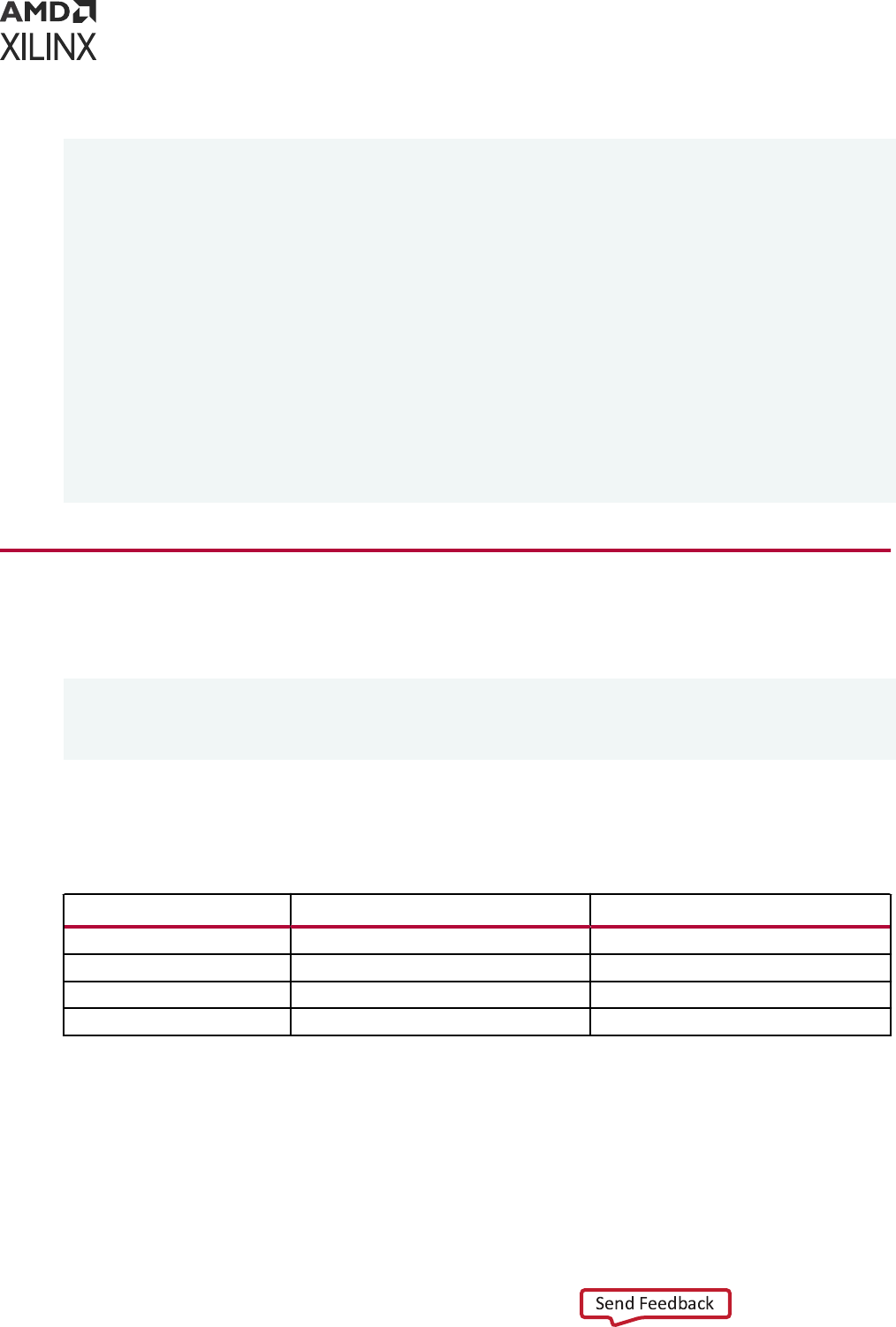
Example code:
// For the following VHDL definitions
// signal slv : std_logic_vector(7 downto 0);
// signal bv : bit_vector(3 downto 0);
// signal s : string(1 to 11);
// type IntArray is array(natural range <>) of integer;
// signal iv : IntArray(0 to 3);
// do the following assignments
//
// slv <= "11001010";
// bv <= B"1000";
// s <= "Hello world";
// iv <= (33, 44, 55, 66);
const unsigned char slvVal[] = {3, 3, 2, 2, 3, 2, 3, 2}; // 3 = '1', 2 = '0'
loader.put_value(slv, slvVal);
const unsigned char bvVal[] = {1, 0, 0, 0};
loader.put_value(bv, bvVal);
const char sVal[] = "Hello world"; // ends with extra '\0' that XSI ignores
loader.put_value(s, sVal);
const int ivVal[] = {33, 44, 55, 66};
loader.put_value(iv, ivVal);
Vivado Simulator Verilog Data Format
Verilog logic data is encoded in C/C++ using the following struct, dened in xsi.h:
typedef struct t_xsi_vlog_logicval {
XSI_UINT32 aVal;
XSI_UINT32 bVal;
} s_xsi_vlog_logicval, *p_xsi_vlog_logicval;
Each four-state bit of Verilog value occupies one bit posion in aVal and the corresponding bit
posion in bVal.
Table 65: Verilog Value Mapping
Verilog Value
aVal Bit Value bVal Bit Value
0 0 0
1 1 0
X 1 1
Z 0 1
For two-state SystemVerilog bit values, an aVal bit holds the bit value, and the corresponding
bVal bit is unused. Xilinx recommends that you zero out bVal when composing two-state
values for xsi_put_value.
Appendix L: Using Xilinx Simulator Interface
UG900 (v2022.1) April 21, 2022 www.xilinx.com
Vivado Design Suite User Guide: Logic Simulation 269
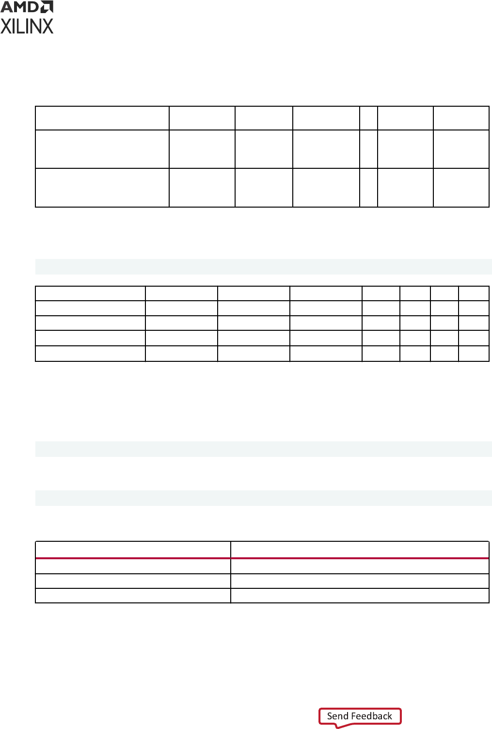
Verilog vectors are organized in C/C++ with the right index of the Verilog vector mapped to
aVal/bVal bit posion 0 and the le index mapped to aVal/bVal bit posion <vector size> -
1
aVal/bVal Bit Position <vector size> to
31
<vector size> -
1
<vector size> - 2 ... 1 0
Index of
wire [left:right] vec
(where left > right)
unused left left - 1 ... right + 1 right
Index of
wire [left:right] vec
(where left < right)
unused left left + 1 ... right - 1 right
For example, the following table shows the Verilog and C/C++ equivalents of the following
Verilog vector.
wire [7:4] w = 4'bXX01;
Verilog Bit Index 7 6 5 4
Verilog Bit Value X X 0 1
C/C++ Bit Position 31 ... 4 3 2 1 0
aVal Bit Value unused ... unused 1 1 0 1
bVal Bit Value unused ... unused 1 1 0 0
The C/C++ representaon of a Verilog vector with more than 32 elements is an array of
s_xsi_vlog_logicval, for which the right-most 32 bits of the Verilog vector maps to
element 0 of the C/C++ array. The next 32 bits of the Verilog vector maps to element 1 of the
C/C++ array, and so forth. For example, the following table shows the mapping of Verilog vector
wire [2:69] vec;
to the C/C++ array
s_xsi_vlog_logicval val[3];
Table 68: Verilog Index Range
Verilog Index Range C/C++ Array Element
vec[38:69] val[0]
vec[6:37] val[1]
vec[2:5] val[3]
Hence, vec[2] maps to val[3] bit posion 3, and vec[69] maps to val[0] bit posion 0.
Appendix L: Using Xilinx Simulator Interface
UG900 (v2022.1) April 21, 2022 www.xilinx.com
Vivado Design Suite User Guide: Logic Simulation 270

A mul-dimensional Verilog array maps to the bits of a s_xsi_vlog_logicval or
s_xsi_vlog_logicval array as if the Verilog array were aened in row-major order before
mapping to C/C++.
For example, the two-dimensional array
reg [7:0] mem[0:1];
is treated as if copied to a vector before mapping to C/C++:
reg [15:0] vec;
vec[7:0] = mem[1];
vec[8:15] = mem[0];
Appendix L: Using Xilinx Simulator Interface
UG900 (v2022.1) April 21, 2022 www.xilinx.com
Vivado Design Suite User Guide: Logic Simulation 271

Appendix M
Additional Resources and Legal
Notices
Xilinx Resources
For support resources such as Answers, Documentaon, Downloads, and Forums, see Xilinx
Support.
Documentation Navigator and Design Hubs
Xilinx
®
Documentaon Navigator (DocNav) provides access to Xilinx documents, videos, and
support resources, which you can lter and search to nd informaon. To open DocNav:
• From the Vivado
®
IDE, select Help → Documentaon and Tutorials.
• On Windows, select Start → All Programs → Xilinx Design Tools → DocNav.
• At the Linux command prompt, enter docnav.
Xilinx Design Hubs provide links to documentaon organized by design tasks and other topics,
which you can use to learn key concepts and address frequently asked quesons. To access the
Design Hubs:
• In DocNav, click the Design Hubs View tab.
• On the Xilinx website, see the Design Hubs page.
Note: For more informaon on DocNav, see the Documentaon Navigator page on the Xilinx website.
References
These documents provide supplemental material useful with this guide:
Appendix M: Additional Resources and Legal Notices
UG900 (v2022.1) April 21, 2022 www.xilinx.com
Vivado Design Suite User Guide: Logic Simulation 272

1. Vivado Design Suite User Guide: Release Notes, Installaon, and Licensing (UG973)
2. Vivado Design Suite User Guide: System-Level Design Entry (UG895)
3. Vivado Design Suite User Guide: Designing with IP (UG896)
4. Vivado Design Suite User Guide: Using the Vivado IDE (UG893)
5. Vivado Design Suite User Guide: Using Tcl Scripng (UG894)
6. Vivado Design Suite 7 Series FPGA and Zynq-7000 SoC Libraries Guide (UG953)
7. Vivado Design Suite Tcl Command Reference Guide (UG835)
8. Vivado Design Suite User Guide: Power Analysis and Opmizaon (UG907)
9. Vivado Design Suite User Guide: Using Constraints (UG903)
10. Vivado Design Suite Tutorial: Logic Simulaon (UG937)
11. Vivado Design Suite User Guide: Design Flows Overview (UG892)
12. Vivado Design Suite Properes Reference Guide (UG912)
13. Vivado Design Suite User Guide: Synthesis (UG901)
14. Wring Ecient Test Benches (XAPP199)
15. IEEE Standard VHDL Language Reference Manual (IEEE-STD-1076-1993)
16. IEEE Standard Verilog Hardware Descripon Language(IEEE-STD-1364-2001)
17. IEEE Standard for SystemVerilog--Unied Hardware Design, Specicaon, and Vericaon
Language (IEEE-STD-1800-2009)
18. Standard Delay Format Specicaon (SDF) (IEEE-STD-1497-2004)
19. Recommended Pracce for Encrypon and Management of Electronic Design Intellectual
Property (IP) (IEEE-STD-P1735)
Links to Additional Information on Third-
Party Simulators
1. Questa Advanced Simulator/ModelSim simulators:
• hp://www.mentor.com/products/fv/questa/
• hp://www.mentor.com/products/fv/modelsim/
2. Synopsys VCS Simulators: hp://www.synopsys.com/Tools/Vericaon/
FunconalVericaon/Pages/VCS.aspx
3. Acve-HDL Simulators: hps://www.aldec.com/en/support/resources/documentaon/
arcles/1579
Appendix M: Additional Resources and Legal Notices
UG900 (v2022.1) April 21, 2022 www.xilinx.com
Vivado Design Suite User Guide: Logic Simulation 273
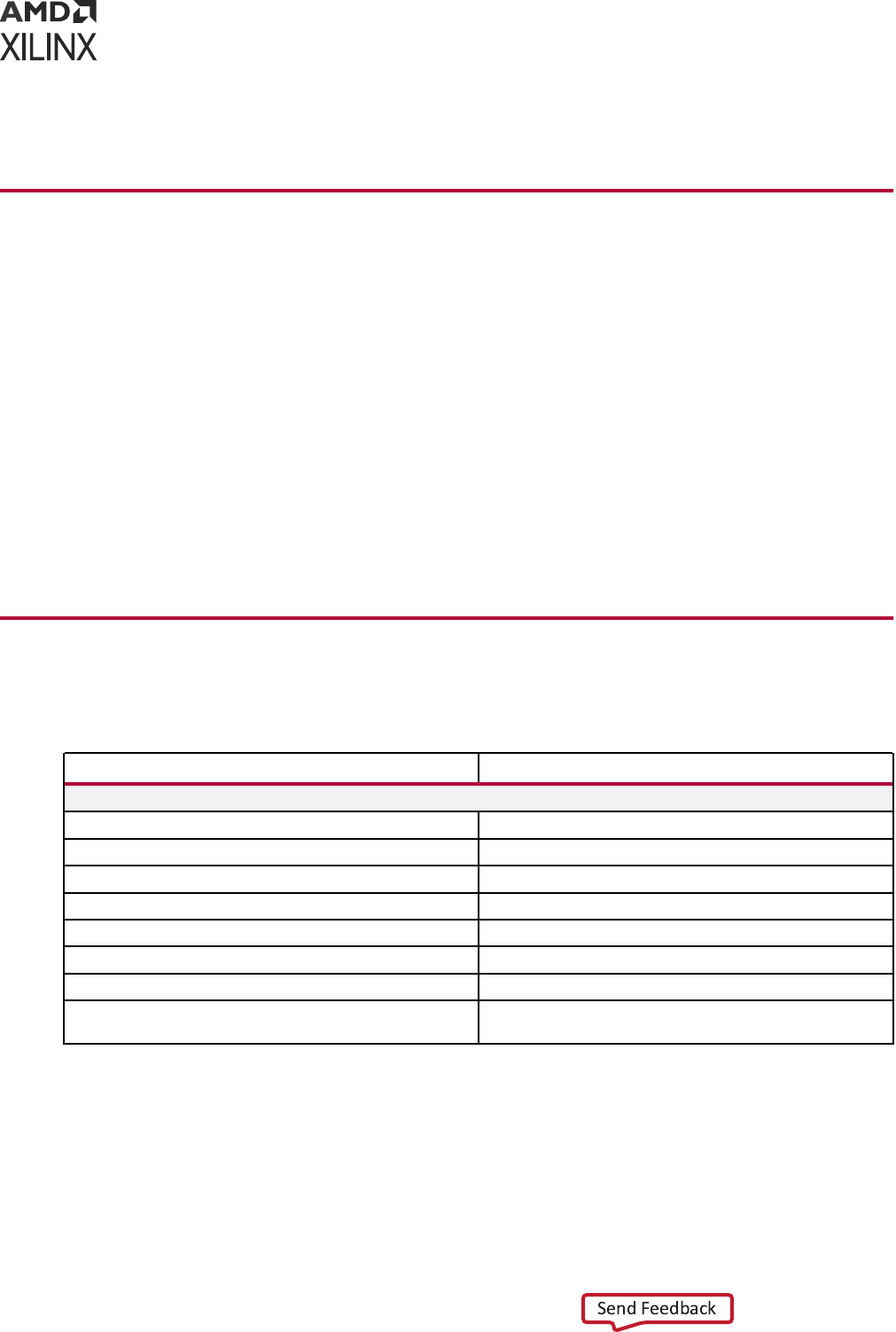
4. Riviera PRO Simulators: hps://www.aldec.com/en/support/resources/documentaon/
arcles/1525
Training Resources
Xilinx provides a variety of training courses and QuickTake videos to help you learn more about
the concepts presented in this document. Use these links to explore related training resources:
1. Designing FPGAs Using the Vivado Design Suite 1 Training Course
2. Designing FPGAs Using the Vivado Design Suite 2 Training Course
3. Designing FPGAs Using the Vivado Design Suite 3 Training Course
4. Vivado Design Suite Quick Take Video: How to use the Zynq-7000 Vericaon IP to verify
and debug using simulaon
5. Vivado Design Suite Quick Take Video: Logic Simulaon
6. Vivado Design Suite QuickTake Video Tutorials
Revision History
The following table shows the revision history for this document.
Section Revision Summary
04/21/2022 Version 2022.1
Supported Simulators Updated Supported Simulators table.
Understanding the Simulator Language Option Updated the content.
Chapter 3: Simulating with Third-Party Simulators Updated the content.
export_simulation Updated the content.
Vivado Simulator Compilation Options Updated the content.
Testbench Feature Updated the content.
Supported Features Updated the content.
Appendix F: SystemC Support in Vivado IDE Updated Protected Models, Unprotected Models, Simulators
Supported for SystemC Simulation
Appendix M: Additional Resources and Legal Notices
UG900 (v2022.1) April 21, 2022 www.xilinx.com
Vivado Design Suite User Guide: Logic Simulation 274

Please Read: Important Legal Notices
The informaon disclosed to you hereunder (the "Materials") is provided solely for the selecon
and use of Xilinx products. To the maximum extent permied by applicable law: (1) Materials are
made available "AS IS" and with all faults, Xilinx hereby DISCLAIMS ALL WARRANTIES AND
CONDITIONS, EXPRESS, IMPLIED, OR STATUTORY, INCLUDING BUT NOT LIMITED TO
WARRANTIES OF MERCHANTABILITY, NON-INFRINGEMENT, OR FITNESS FOR ANY
PARTICULAR PURPOSE; and (2) Xilinx shall not be liable (whether in contract or tort, including
negligence, or under any other theory of liability) for any loss or damage of any kind or nature
related to, arising under, or in connecon with, the Materials (including your use of the
Materials), including for any direct, indirect, special, incidental, or consequenal loss or damage
(including loss of data, prots, goodwill, or any type of loss or damage suered as a result of any
acon brought by a third party) even if such damage or loss was reasonably foreseeable or Xilinx
had been advised of the possibility of the same. Xilinx assumes no obligaon to correct any
errors contained in the Materials or to nofy you of updates to the Materials or to product
specicaons. You may not reproduce, modify, distribute, or publicly display the Materials
without prior wrien consent. Certain products are subject to the terms and condions of
Xilinx's limited warranty, please refer to Xilinx's Terms of Sale which can be viewed at hps://
www.xilinx.com/legal.htm#tos; IP cores may be subject to warranty and support terms contained
in a license issued to you by Xilinx. Xilinx products are not designed or intended to be fail-safe or
for use in any applicaon requiring fail-safe performance; you assume sole risk and liability for
use of Xilinx products in such crical applicaons, please refer to Xilinx's Terms of Sale which can
be viewed at hps://www.xilinx.com/legal.htm#tos.
AUTOMOTIVE APPLICATIONS DISCLAIMER
AUTOMOTIVE PRODUCTS (IDENTIFIED AS "XA" IN THE PART NUMBER) ARE NOT
WARRANTED FOR USE IN THE DEPLOYMENT OF AIRBAGS OR FOR USE IN APPLICATIONS
THAT AFFECT CONTROL OF A VEHICLE ("SAFETY APPLICATION") UNLESS THERE IS A
SAFETY CONCEPT OR REDUNDANCY FEATURE CONSISTENT WITH THE ISO 26262
AUTOMOTIVE SAFETY STANDARD ("SAFETY DESIGN"). CUSTOMER SHALL, PRIOR TO USING
OR DISTRIBUTING ANY SYSTEMS THAT INCORPORATE PRODUCTS, THOROUGHLY TEST
SUCH SYSTEMS FOR SAFETY PURPOSES. USE OF PRODUCTS IN A SAFETY APPLICATION
WITHOUT A SAFETY DESIGN IS FULLY AT THE RISK OF CUSTOMER, SUBJECT ONLY TO
APPLICABLE LAWS AND REGULATIONS GOVERNING LIMITATIONS ON PRODUCT
LIABILITY.
Copyright
© Copyright 2012-2022 Xilinx, Inc. Xilinx, the Xilinx logo, Alveo, Arx, Kintex, Kria, Spartan,
Versal, Vis, Virtex, Vivado, Zynq, and other designated brands included herein are trademarks of
Xilinx in the United States and other countries.
Appendix M: Additional Resources and Legal Notices
UG900 (v2022.1) April 21, 2022 www.xilinx.com
Vivado Design Suite User Guide: Logic Simulation 275

AMBA, AMBA Designer, Arm, ARM1176JZ-S, CoreSight, Cortex, PrimeCell, Mali, and MPCore
are trademarks of Arm Limited in the EU and other countries.PCI, PCIe, and PCI Express are
trademarks of PCI-SIG and used under license. All other trademarks are the property of their
respecve owners.
Appendix M: Additional Resources and Legal Notices
UG900 (v2022.1) April 21, 2022 www.xilinx.com
Vivado Design Suite User Guide: Logic Simulation 276
